This thread has been locked.

If you have a related question, please click the "Ask a related question" button in the top right corner. The newly created question will be automatically linked to this question.

TPS54335A: variable Uout

Part Number: TPS54335A
Other Parts Discussed in Thread: LM3409

Hi!

I try to get a variable output voltage for LEDs (0A..1A2). I did not choose the LM3409, because: It use a diode (D1 on the first page of the datasheet)  instead of a FET for the current from ground to the coil...

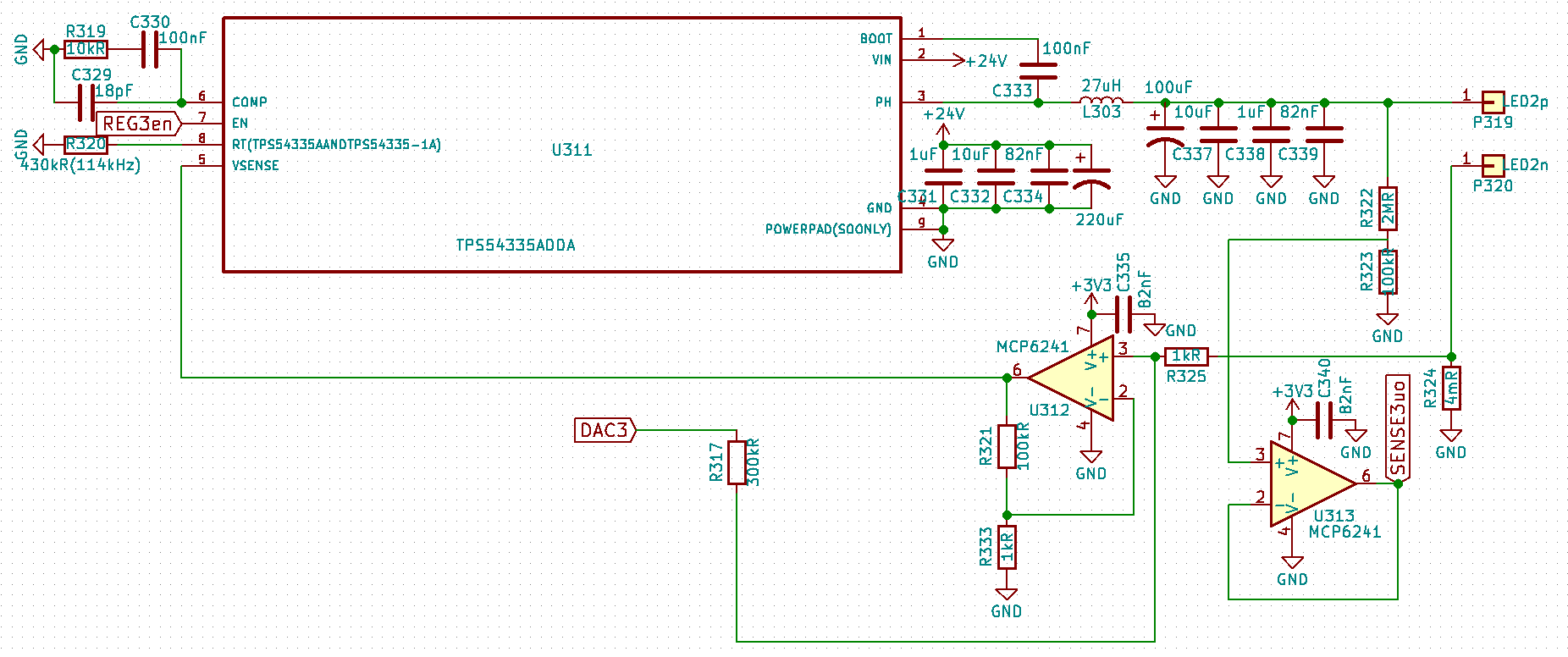
Therefore I use an opamp (see appendix),

  1. whose output is connected to VSENSE,
  2. whose positive input is connected to a voltage divider that is connected to a low side current sense resistor (4mR) and a DAC output (0V..2V4), and
  3. whose negative input is connected to a voltage divider (1kR/100kR) that is connected to ground and the output of the opamp.

it works quite good until the output current reaches about 50%. Above 50% the output current is oscillating between 0% and 50% at about 2Hz.

It seems to get better with a 5R resistor instead of the 12V LED.

Furthermore a higher frequency (e. g. 350kHz instead of 114kHz) and a higher C4 (300nF instead of 100nF) seem to help (but i m afraid that the postal radio frequency inspectors go postal, when I do that all day).

Why is that?

How can i fix my design?

Thx.

Bye

Arne

PS: www.falstad.com/.../circuitjs.html

  • Hi,

    Can you upload the full application circuit for better understanding? you may send email to us if there concern on IP.

    my email add.: andy.chen@ti.com
  • yup...

    i made the pictures with KiCAD and GIMP:

    schematics

    top copperbottom copper

    -arne

  • Hi
    Your application is below, right?
    Vin 24V
    Vout 12V
    LED Load 2A -max
    Fsw=114KHz

    How do you calculate the compensation network on COMP pin? the calculation procedure on data sheet is for voltage output, not for current source output.

    You may try first to change C329 from 18pF to 1nF--4.7nF to see if any improvement.

    Can you test PH node waveform when circuit unstable?
  • Hi!

    Yes, u r right... but Vout is between 5V and 14V (for 4 blue LEDs in series; red/green/blue can use up to 1A; and white up to 2.4A...)...

    I tried 2nF as C329 instead of 18pF, but it did not help... I think my feedback circuit causes the problem...

    I changed the range of DAC3 now: it is between 1.2V and 2.4V... i think the opamp U312 does not like it, when its positive input is too close to 0V... in addition i had to decrease the amplification factor of U312 (R333 is 1.43kR now)...

    now it works better

    • up to 10V with a purely ohmic 10R load and
    • up to 8V (3 red LEDs at 1A), BUT:
    • that 12V white LED still flickers...

    could a large R319 (in the COMP-pin circuit) help?

    or is it more like my feedback circuit is not so good for higher Vout?

    For the values  of R319, C330, C329 i used the C program in the appendix... I chose a value that was somewhere in the middle... *giggle*

    -arne

    appendix:

    #include <math.h>
    #include <stdio.h>
    #include <stdlib.h>
    
    int main(int argc, char ** argv) {
    	if (argc!=3) return 1;
    	double vmax = atof(argv[1]);
    	double vstep = vmax/5;
    	double imax = atof(argv[2]);
    	double istep = imax/5;
    	double co = 121e-6;
    	double f = 114e3;
    	double fc = f/10;
    	double re = 5e-3;
    	for (double v=vstep; v<=vmax; v+=vstep) {
    		double r4 = 2*M_PI*fc*v*co / ((1300e-6)*8*.8);
    		printf("v:%4.1fV r4:%4.1fkR",v,r4*1e-3);
    		for (double i=istep; i<=imax; i+=istep) {
    			double rl = v/i;
    			double c4 = rl*co / r4;
    			double c6 = re*co / r4;
    			printf(" | %3.0fnF %3.0fpF",c4*1e9,c6*1e12);
    		}
    		printf("\n");
    	}
    	return 0;
    }
  • Hi!

    Today i found a solution to my problem:
    I just added a 2nF capacitor in parallel to R321 and now my little pocket oscilloscope shows a straight line, when I connect ohmic loads. *w00t* :)
    The compensation network was not the problem...

    Thx.

    Bye
    Arne
  • Hi,

    Good approach!

    Actually the cap on R321 will add an additional pole in control loop, it's equivalent to modify C329 but may need to redesign whole compensation network.
  • Hi!

    the last time i heard a control engineering lecture is about 20 years ago... giggle

    but i still remember that one needs a sufficiently accurate model of the whole system (in the form of 2 polynoms, where one is divided by the other), before one can start compensating the "bad" poles... :)

    i just thought, that the output of the opamp might be "flaky", because its VIN+ is so close to negative supply rail... furthermore the negative supply rail has a lot of noise (because of the switching), i guess... lol

    -arne