This thread has been locked.

If you have a related question, please click the "Ask a related question" button in the top right corner. The newly created question will be automatically linked to this question.

bq34110: Minimum parameters that need to be changed. How to change default Full Charge Capacity.

Part Number: BQ34110

Hi,

I'm working on development with bq34110evm-796, and I specifically need help with configuration of the gauge to obtain accurate gauging with my battery pack. My questions are:

1) I watched training.ti.com/gauge-programming-fundamentals , where it is said that each Gauge has a minimum set of parameters that need to be changed to account for a particular battery. The datasheet and TRM are not clear about which these parameters are. So I changed the following ones based on battery datasheet and charger datasheet:

Addres  Name                                           Value
0x408A Design Capacity mAh                 1700 mAh
0x40C0 Learned Full Charge Capacity    1700 mAh
0x425A Fixed EDV0                                 3000 mV
0x4114 Charge Voltage T1T2                  4000 mV (*)
0x4116 Charge Voltage T2T3                  4000 mV (*)
0x4118 Charge Voltage T3T4                  4000 mV (*)
0x4120 Taper Voltage                              100 mA
0x411C Taper Current                              45 mA
0x411E Minimum Taper Capacity             0 mAh

(*) The charger I'm using LTC4064 charges to 4V.

Am I missing any necessary parameter?

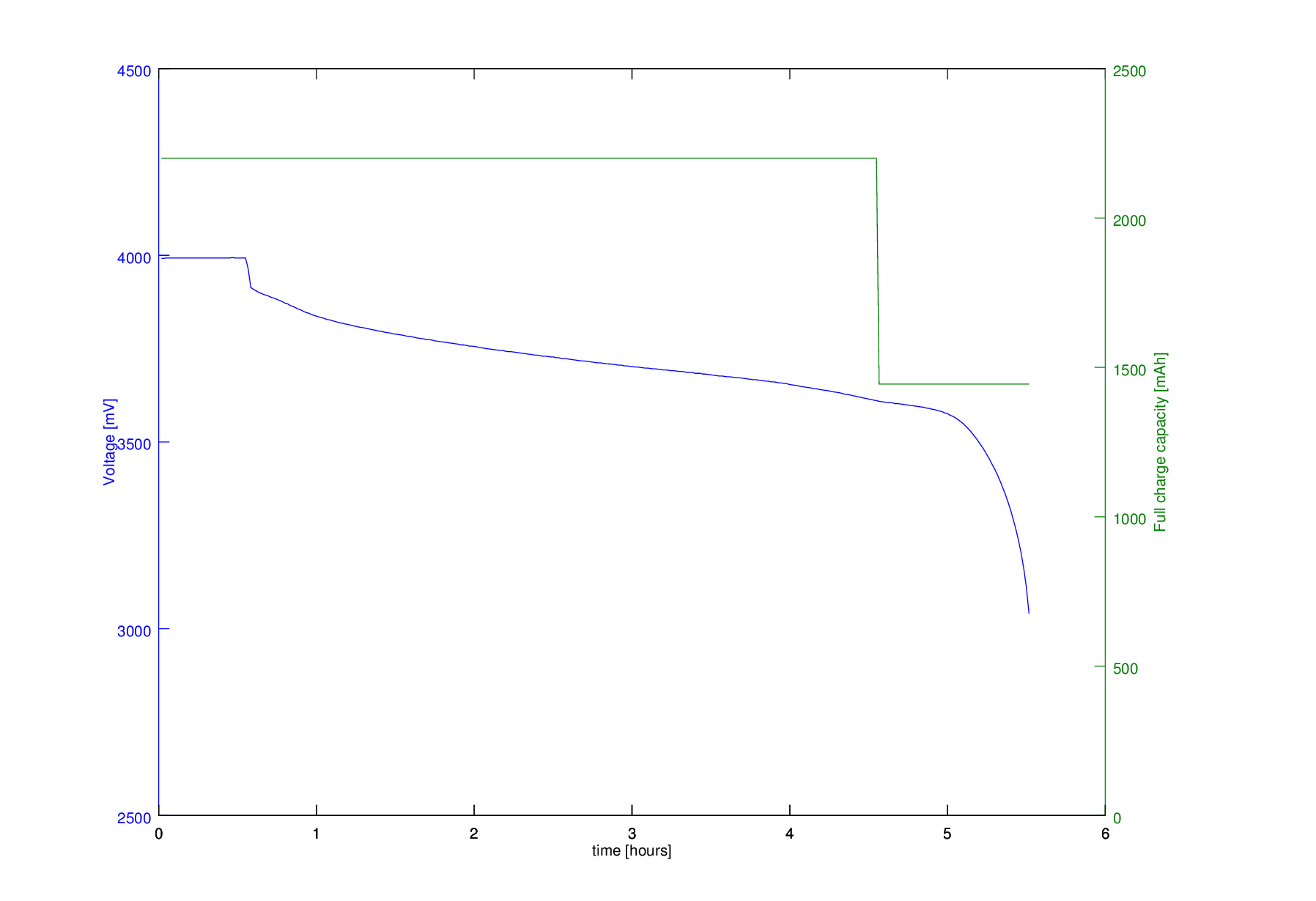
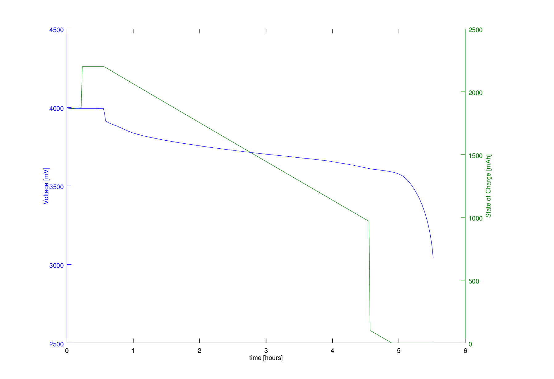
2) After setting the parameters above I performed a full discharge (qualified discharge) and logged the data. I attach the graphs. I found that Full Charge Capacity (FCC) was 2200mAh from the begining, and around EDV2 it adjusted down to 1444 mAh. I know the BQ34110 updates the battery capacity on every qualified discharge, so I expected that writing 1700 mAh into Learned Full Charge Capacity would set the initial learning state to my nominal capacity of 1700 mAh, which it didn't.

In powerpoint "Common issues and solutions.ppt" page 13, I understand that after a learning cycle, some register in flash memory contains this learned condition, and may be then part of the Golden Image to be programmed to each GG and work as the initial condition.

Which is the parameter (Address / Name) that I have to change so that the Full Charge Capacity starts with 1700 mAh instead of the default 2200 mAh even in the first qualified discharge?

3) In production, batteries are usually stored in stock with around 50% charge. So the first time that the product is turned on, the state of charge will be around 1700mAh / 2 = 850 mAh. The first discharge shouldn't be a qualified discharge, because RC < FCC – Near Full, but in order for the BQ34110 to make this judgement I should be able to store FCC = 1700 mAh, and SOC = 850 mAh, as an initial condition.

How can I set this initial condition?

4) What should the manufacturer and/or the client perform as a first turn on of the product? Are any of these expected to perform a full discharge or charge cycle?

Thanks,

Gustavo

  • Hi,
    Regarding my Questoin (2), I have some further doubts:

    In TRF, page 25, it says:

    "Full Charge Capacity (FCC)—Last measured discharge capacity of the battery
    FCC is the last measured discharge capacity of the battery. It is represented in units of mAh. On
    initialization, the bq34110 device sets FullChargeCapacity() to the data flash value stored in
    Learned Full Charge Capacity (FCC), which should be initialized using the same units. During
    subsequent discharges, the bq34110 device updates FullChargeCapacity() with the last measured
    discharge capacity of the battery. The last measured discharge of the battery is based on the value
    in the DCR after a qualified discharge occurs. Once updated, the bq34110 device writes the new
    FullChargeCapacity() value to data flash to Learned Full Charge Capacity. FullChargeCapacity()
    represents the full battery reference for the state-of-charge calculations."

    Also, on page 31, it says:

    "2.7.10 Initial Battery Capacity at Device Reset
    The bq34110 device estimates the initial capacity of a battery pack at device reset, which is the case
    when battery cells are first attached to the application circuit. The initial FullChargeCapacity() (FCC) is a
    direct copy of the data flash parameter Learned Full Charge Capacity."

    So, my Question (2) becomes:

    2.1) What does "initialization" mean?
    2.2) When does this copy from Learned FCC to FCC occur?
    2.3)Is there any [power up + configuration + battery attachment] sequence that must be followed?
    2.4) How is the Learned FCC register written before the first battery attachment? How should the GG be powered during configuration?

    Regarding my Question (3):
    In TRM, page 31, it says "The initial RC is estimated using the voltage characteristics of the programmed battery voltage table (see Voltage 0% DOD through Voltage 100% DOD) and Learned Full Charge Capacity."
    So this answers my question (3).

    Summing up, I still have Questions (1), (2.1 to 2.4 in this reply), and question (4).

    Thanks,
    Gustavo
  • Hi Gustavo,

    Thank you for the very thorough post. With this many questions, it will take some time to respond fully. I should have an answer ready by Friday.

    Thank you!

    Sincerely,
    Bryan Kahler
  • Hi Gustavo,

    Thank you for your patience:

    Q1. This is a good list of parameters to begin modifying. Please make sure to modify the parameters discussed in Section 2 of the device TRM. Please pay particular attention to the CEDV Parameters found in Section 2.7.9 of the TRM found at: http://www.ti.com/lit/sluubf7
    Q2. With this reserved capacity you will need to determine where the EDV2 point should sit. Normally, when using the full capacity of the battery, this point will be at 7% of state of charge (SOC).

    FCC (new) = DCR (final) = DCR (initial) + Measured Discharge to EDV2 + (FCC × Battery_Low%)

    Please find the SOC value on a graph where your device sits at your extra reserve, and EDV0 (which is normally at 0%). You will determine this by graphing your passed charge. Normalize around your new 0% value for EDV0. Find EDV1 using passed charge normalized around EDV0 where EDV1 is set at 1% of SOC. Similarly, set EDV2 at the 7% value of SOC.

    In step format:

    0. Please make sure Max Charging Voltage is set to 4000 mV.
    1. Discharge the battery to empty (terminate voltage from the datasheet).
    2. Reset your device to clear out the passed charge value and begin logging at 1 second intervals
    3. Charge to full with your 4v charger
    4. Graph pass charged vs voltage from the logs
    5. Set EDV0 to the terminate discharge voltage (this is the voltage you started at before turning on your charger)
    6. Set EDV1 to the voltage that corresponds to 1% of passed charge.
    7. Set EDV2 to the voltage that corresponds to 7% of passed charge.

    Q3. Please set Rem Cap Init Percent. More information may be found in Section 2.7.10 of the TRM.

    Q4. The end user should either charge or discharge the battery through use until RC sets. A learning cycle with be performed when the user discharges the battery from full charge. A maintenance cycle may be specified, but is by no means a requirement.

    Sincerely,
    Bryan Kahler
  • Thank you Bryan,

    Regarding Q1, the minimum set of parameters that should be modified for the case of a 2-cell pack, is it the same for the 1-cell case? I'm asking this because many parameters that I'm using are voltages that seem to be adequate for 1 cell, e.g.,

    - EDV0, EDV2 & EDV2 are 3031, 3385, 3501mV

    - Charging voltages are 4000mV-4200mV

    - Battery Low Set Threshold

    - Smoothing Start Voltage

    Are this absolute voltages for the entire battery pack, or voltages relative to 1 cell?

    Do I have to multiply all of this parameters by number of cells and write them back in the data flash? Some of them don't accept values higher than 5000mV, but others do accept values up to 32767mV.
    Or are they relative to 1-cell, even in the case of multi cell case? I would expect this since there's a parameter called "Number of Series Cells".

    Thanks you,
    Gustavo

  • I need clarification on whether the voltage-dependent minimum set of parameters to be changed should be scaled up by 2 in the case of 2 cells, by 3 in case of 3 cells, etc. I mean, for example, EDV0, EDV1, EDV2, charging voltages, smoothing voltages, etc.
    Some of these parameters don't accept values higher than 5000mV, which would suggest that they are normalized to 1 cell voltages, but others do accept values up to 32767mV, which would suggest that they are not.

    Or are they automatically scaled based on "Number of Series Cells"?

    In fact this question applies not only to the minimum set of parameters, but to all voltage-dependent parameters.

    Thanks,
    Gustavo
  • Gustavo,
    They are scaled based on the number of series cells.
    thanks
    Onyx