This thread has been locked.

If you have a related question, please click the "Ask a related question" button in the top right corner. The newly created question will be automatically linked to this question.

TPS703: Regarding Biasing circuit of TPS70302 LDO.

Part Number: TPS703

Dear Sir/Mam,

I am working on project in which I want Variable voltage near 1.8Volts and 3.3Volts.

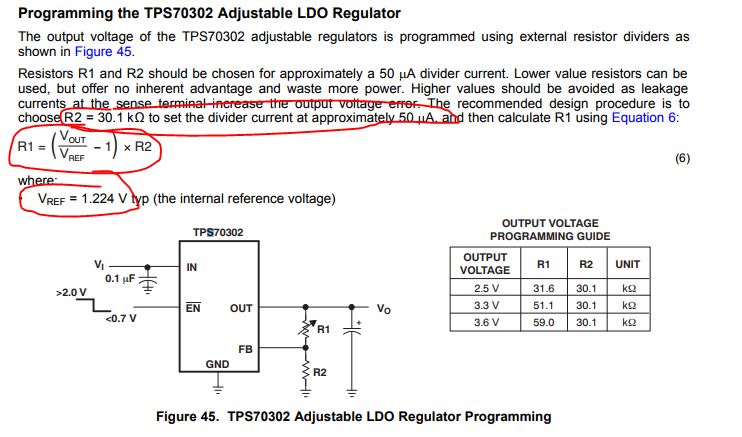
I choose to work with TI's TPS70302 LDO.  

In datasheet of TPS70302 on Page number 35th Adjustable LDO Regulator Programming circuit is giving. I thoroughly read its datasheet. But still I have some doubts.

So, Please provide me 

1) Ideal values of R1 and R2 for 1.8Volts (Vref is 1.224Volts) just like you mentioned R1 and R2 values for 2.5V, 3.3V, 3.6V.

2) Complete Circuit diagram showing all pins Biasing just like you provided for TPS70351 PWP on Page Number 2.

Thank You,

Regards,
Suraj
Second Year MTech Student,
DESE, IISc Bangalore. 
  • Hi Suraj,

    Using Equation 6 from the datasheet, we are able to calculate R1.  R2 is set to be 30.1 k as stated in the datasheet so that the divider current is ~50 uA.  As you mention Vref is 1.224 V.

    R1 = ((Vout / Vref) - 1) x R2

         = (1.8 / 1.224) -1) x 30.1 k

         = 14.16 k

    The closest 1% resistor is 14.0 k.

    A complete schematic will vary by application due to application specific requirements.  You are the best person to decide how much capacitance, headroom (Vin - Vout), etc. is required for your application.  The only difference between the fixed devices on the datasheet such as TPS70351 and the adjustable device TPS70302 is that the adjustable device has feedback pins instead of sense pins.  The feedback pin should be tied to the center of your resistor divider as shown in Figure 45:

    Very Respectfully,

    Ryan