This thread has been locked.

If you have a related question, please click the "Ask a related question" button in the top right corner. The newly created question will be automatically linked to this question.

BQ40Z60: Charging process

Part Number: BQ40Z60
Other Parts Discussed in Thread: BQ40Z50-R2, EV2400, GPCCHEM, BQSTUDIO

Hello Dear TI team

I have some problems with my custom bq40z60 board again. Now problems with charging occured. 

The biggest problem is probabbly that I don't fully understand, how it should work.

I thought that, I will plug in AC adapter(I tried 20 V) and gauge will do everything for me. But it doesn't seem like that. When I plug in Adapter, it won't charge batteries.

I tried run my bq40z60 PCB without batteries, just with adapter and I measured output voltage 17,4 instead of 16,8 volts (I have 4 batteries in series - 4,2 [V] * 4 = 16,8).

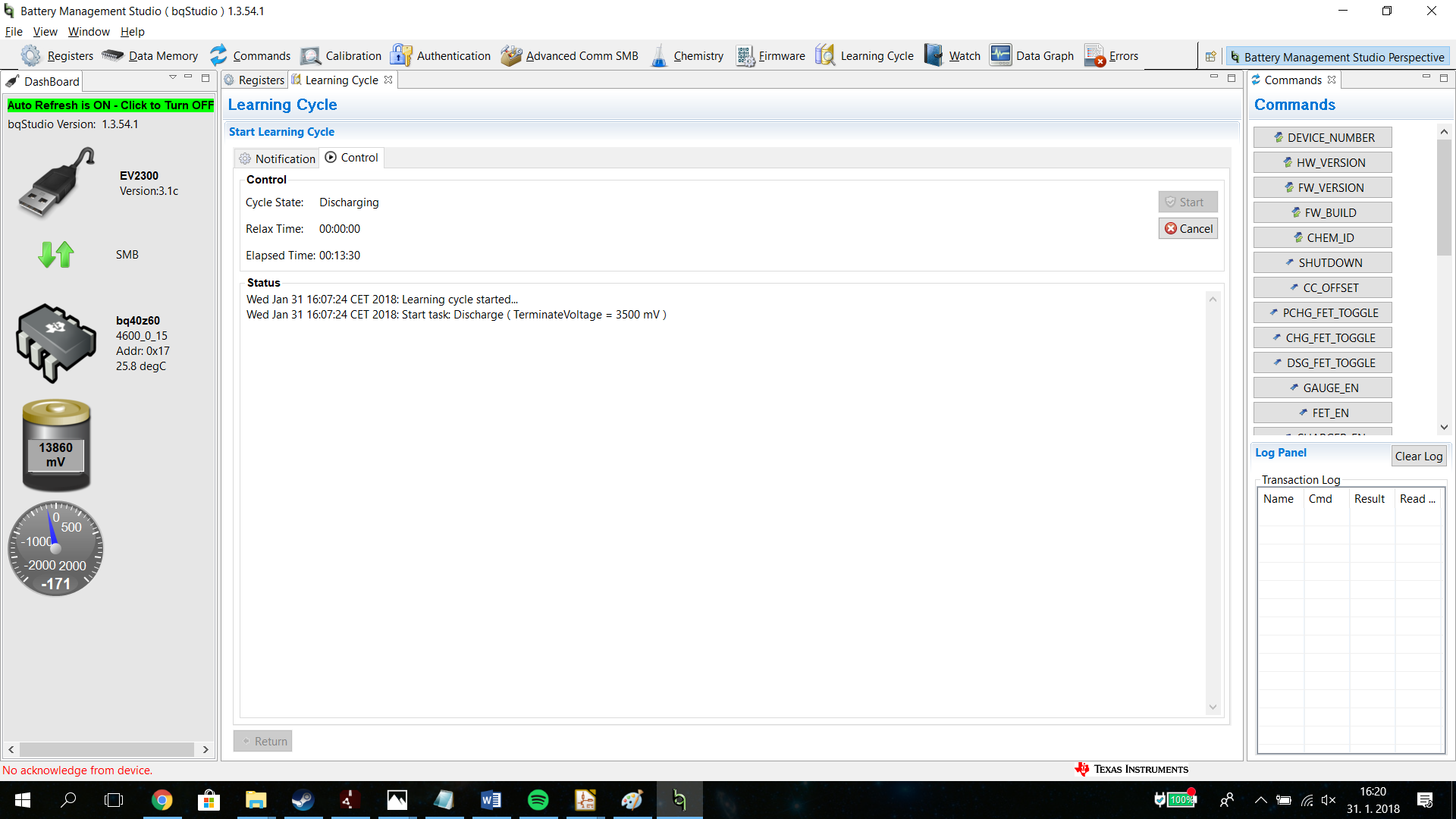
So I realized that, I have to do it through Learning cycle. But It won't stop discharging.

As it is shown in 2 pictures below, I set 3,5 V as termination voltage, but it was still discharging.

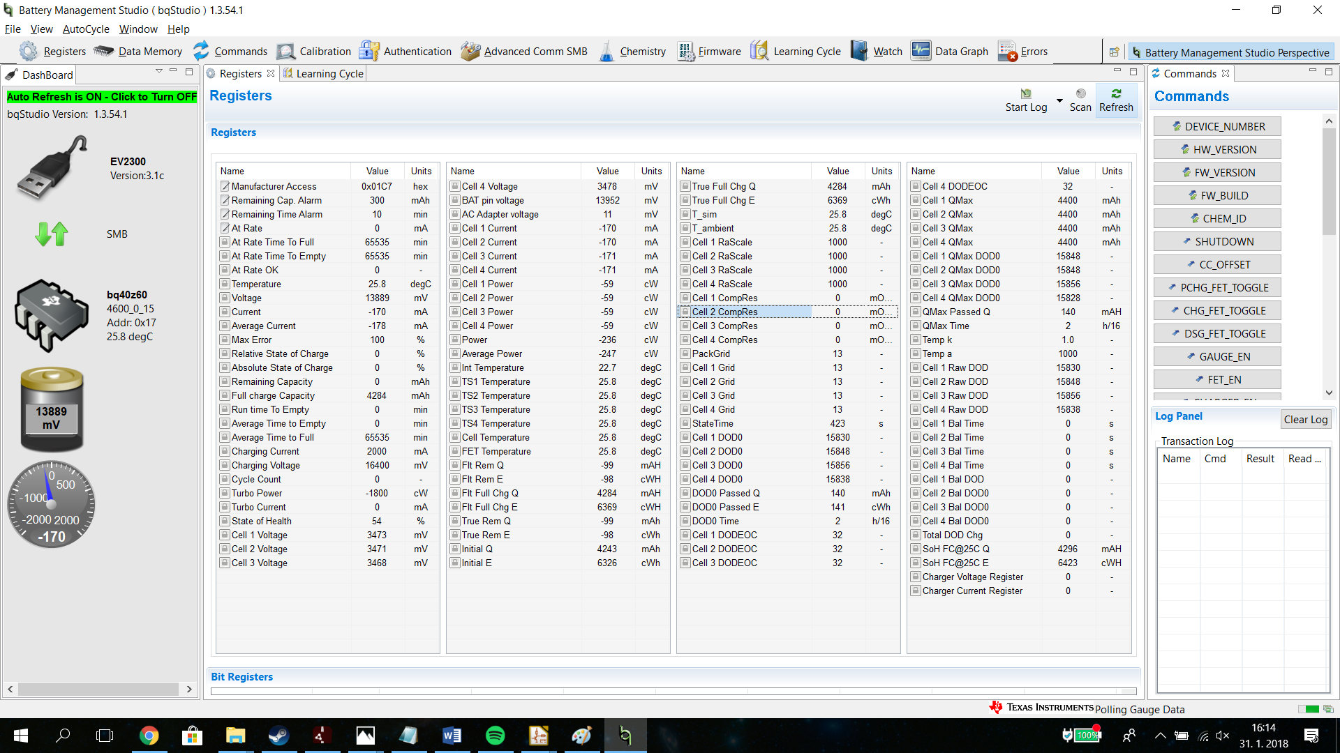
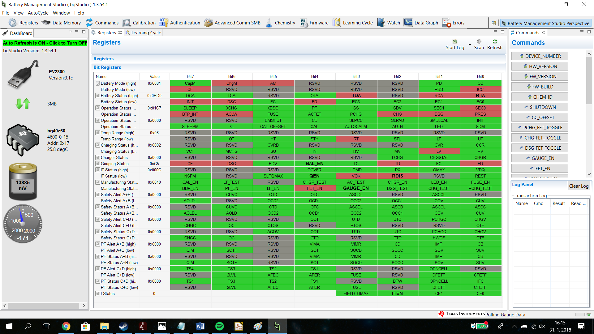
register values are attached below

For better orientation i would rather sum up my questions in points

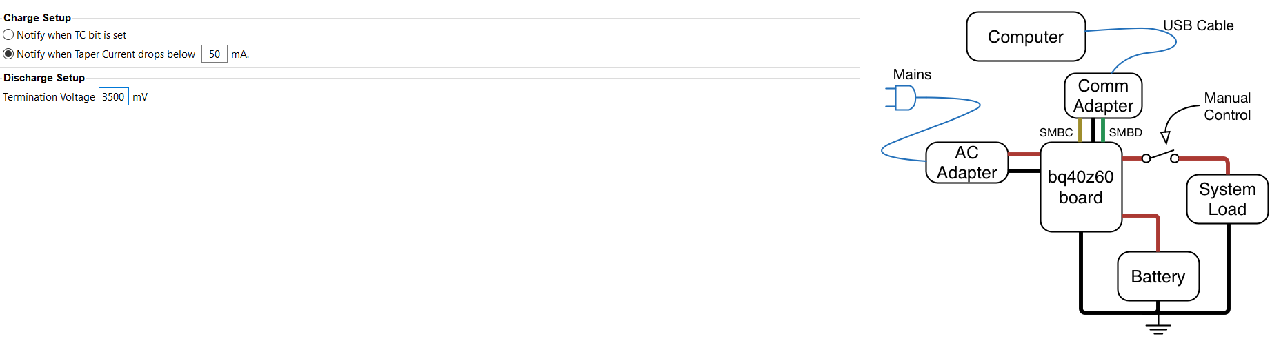
1) What exactly shoud the bq40z60 do, when I plug in adapter, and what is optimal voltage? Are 20 V OK (for my 4S1P) ?

2) Is it necessary to run learning cycle for charging battery ?

2) How to run learning cycle properly, when my battery is not fully charge, and I don't want to discharge it to much

3) What does Manual option mean (instead of automatic) for learning cycle ? Does it mean, I have to disconnect Load after discharge? Because there are FETs, that can eliminate current from batteries to the load.

So, when I chose Manual, I have to be with my board and when batteries are discharged, I have to be there and disconnect load ?

And can I rely on that it stops discharging on 2.9 Volts ? Becouse as it is shown on the 2nd picture, it was still discharging, when its voltage was below set 3,5 [V]

4) Can I limit current with Max Current Register ? Or what exactly this register does?

I attached .srec file.

Thank you for any help !

Regards Ondrej31_1_2018.zip

  • Hi Ondrej,

    Before you get too far along with your design using bq40z60 we would like to make sure you have considered all of the options as well as the challenges of working with a such a tightly integrated solution.

    We have found that many customers using bq40z60 have difficulty designing their board to pass EMI testing. This is due to the limited degree of freedom you have when laying out such an integrated solution which includes a switch-mode device. As attractive as it may sound to have the charging, gauging, and protection functions in one IC, in practice by using a separate charger and a separate gauge you get more flexibility and it can actually be easier to design. Not only can you choose from a wider range of chargers and gauges, but you can take advantage of newer technology and newer firmware. Popular choices for discrete multi-cell chargers range from standalone ones with integrated FETs like bq2417x or external FETs (for higher currents) like bq2461x to SMBus/I2C controlled chargers like bq2477x, among many others. The newest and most interesting charger is the buck/boost charger bq2570x which allows you to take any voltage input and charge any battery voltage stack, as well as take that battery voltage and boost or buck it back out to any target voltage. It’s great for USB Type-C and USB-PD applications. On the gauge side, the most popular new standalone gauge is bq40z50-R2 which has the most recent feature set and more extensive safety and protection options.

    Of course TI is here to support you no matter which ICs you choose, but be sure to consider all of your options and don’t assume that integration is always the best.

    The following should answer your questions, and some you didn't ask :)

    0. *VERY IMPORTANT - PERFORM IMMEDIATELY* Please ensure that the firmware on your EV2300/EV2400 is up to date. If your EV2300 is using v. 3.1C (as shown in your screenshots), the updated firmware and instructions can be found here: e2e.ti.com/.../3225.EV2300FWUpdaterUnprogDev.zip
    1. Please follow the EVM User's Guide for initial device bringup: http://www.ti.com/lit/sluub71
    2A. It is necessary to run a learning cycle for the IT algorithm utilized by the gauge. Here is a great little guide for a different gauge (the process is similar): http://www.ti.com/lit/slua777
    2B. You will need to fully discharge the battery. Please refer to the instructions found with the GPCCHEM tool: http://www.ti.com/tool/gpcchem
    3. Yes, the manual option is if you don't want to use external relays to control a power supply and electronic load. Please use an electronic load set with a constant current with a terminate voltage option. On some electronic loads this will be marked by the term 'battery'. In the screenshot shown above, your bqStudio will also perform this function, but not in manual mode (as you are now the relay).
    4. If you're referring to the Advanced Charge Algorithm > Charger > Max Current Register, this register sets the current limit of the charger when the CHG FET is disabled, meaning that the battery is fully charged or charge is inhibited for some reason. For more information, please refer to Section 4.2 of the TRM found here: http://www.ti.com/lit/sluua04

    Sincerely,
    Bryan Kahler
  • Thank you very much for your reply!


    I will use your advice in my next project. I thought that one IC like BQ40Z60 will make it simple.


    thanks for answering all my questions. Now I have my PCB in laboratory at university. At tuesday I will be able to discharge cells and possibly charge.

    I have one more problem that I forgot highlight.

    When I tried run my bq40z60 PCB without batteries, just with adapter I measured output voltage 17,4 instead of 16,8 volts (I have 4 batteries in series - 4,2 [V] * 4 = 16,8).

    Is that voltage ok? Because I am a bit concerned about connecting the batteries to this voltage.

    Thanks for any help

    Regards Ondrej
  • Hi Ondrej,

    Was this measurement during charging? Was it with a multimeter or with the gauge? If with the gauge, has it been calibrated?

    Often the charging voltage is higher than that of the rested open cell voltage of the stack. Please make sure that this voltage is permissible per your battery datasheet.

    Limits can be set for the device using bqStudio.

    Sincerely,
    Bryan Kahler
  • Hi,

    no that measurement was not during charging. it was measured, whan was connected only adapter. it was with both of them., multimeter and gauge. 

    maybe it were badly calibrated. I will try it again as soon as I will repair PCB. I destroyed some transistors so I have to replace them

    I wanted to update ev2300 but i noticed that I need 2 ev2300. is there any chance for update ev2300 without the other one ? and is it realy big problem ?

    Thank you very much for your help. I will try set limits again. I hope then will be voltage OK.

    In any case, I will write the result.

    Regards Ondrej

  • Hello

    I am sorry that I didn't write anything for so long.

    I decided (on your advice) to use other IC, so thank you for your time and help

    Regards,

    Ondrej