This thread has been locked.

If you have a related question, please click the "Ask a related question" button in the top right corner. The newly created question will be automatically linked to this question.

UC28025: Soft Start Inquiry

Part Number: UC28025

Hi Team,

Good day! 

My customer is using our UC28025 for their project and have an inquiry on the soft start below:

We are currently tuning the soft start using your controller.

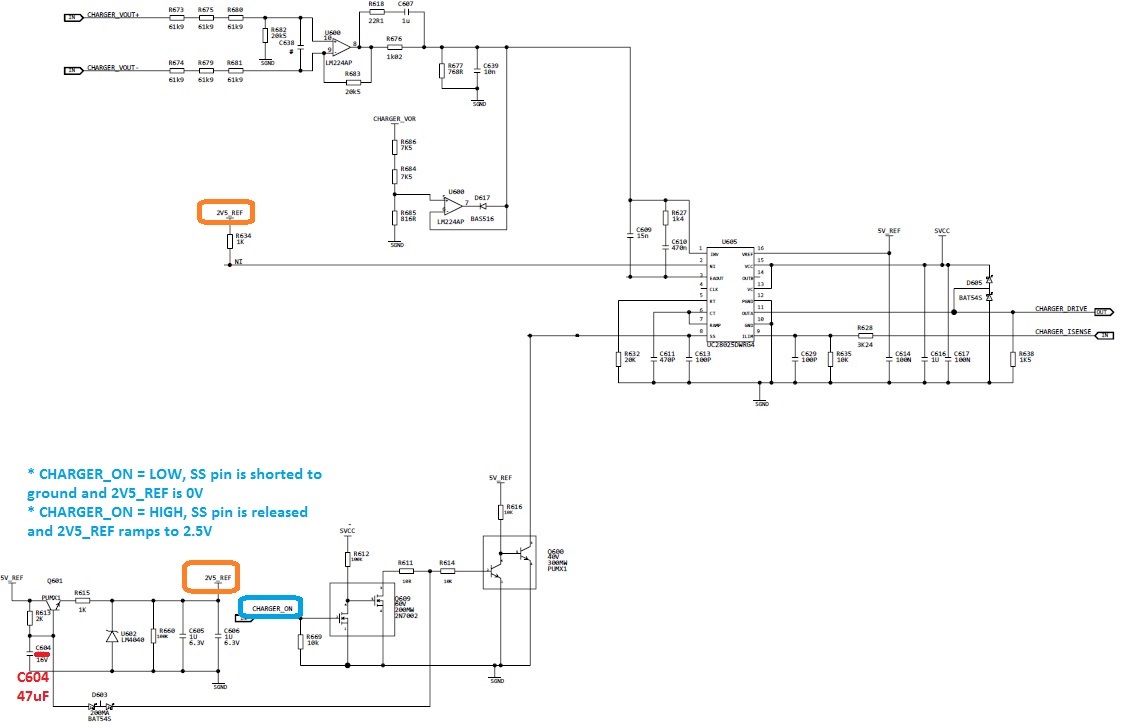
Attached is the schematic in our application.

We are using the CHARGER_ON signal to release SS pin and begin the soft start sequence. We do not seem to have trouble with this.

However, we do find it odd that the OUTA pulses only start  15msec after the SS pin has gone high.

Is this normal?

We are expecting that the OUTA pulses will start as soon as the SS pin is high. Is there an internal delay of some sort that prevents this from happening?


We are currently tuning the soft start by changing the value of C604—thereby delaying the 2.5V external reference’s rise time.

We want to delay the rise time of Vout as much as possible and to avoid having high overshoot.

Thanks! 

Best Regards,

Alfred

  • Hi Alfred,

    Thanks for your interest in UCC28025. There is an internal 1.25V offset applied to the ramp signal which means that the output of the error amplifier must be greater than 1.25V before you see any switching. Can you check the voltage on the EAOUT pin to see when begin to see switching in relation to the output of the error amplifier?

    I would suggest increasing the capacitance of C613. This will slow down how quickly the SS voltage rises and will allow the duty cycle to ramp up much more slowly when you begin switching.

    Best Regards,
    Ben Lough
  • Hi Ben,

    Thanks for the response! Here is our feedback:

    Note that the waveforms below are taken from another test unit having with a different rise time for SS pin, but the test method remains the same and the timing difference between SS pin high and OUTA pulses are also present.


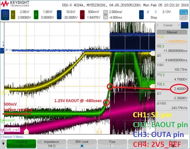
    1. Waveform 1:
    • The EAOUT pin starts at 500mV. The 1.25V level is reached 480usec before OUTA pulses start. By the time OUTA pulses start, EAOUT is already ~2.4V. Is this your expected response?
    • Based on the statement of your BU, the output of the error amplifier must be greater than 1.25V before you see any switching”, I was expecting that the OUTA pulses will start as soon as EAOUT pin is greater than 1.25V

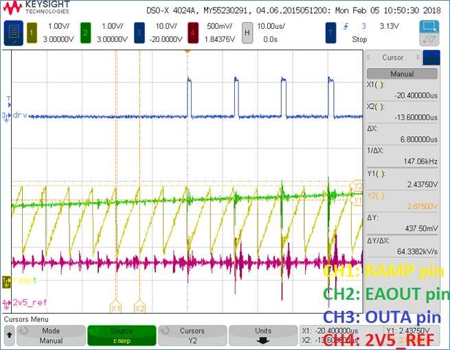
    2. Waveform 2:

    • Time frame captures when OUTA first outputs a pulse.
    • Shows the RAMP waveform superimposed on the EAOUT waveform.

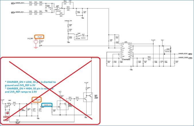
    3. Question regarding SS ramp time (refer to schematic below):

    • If the delay on the 2.5V external ref were removed and simply control the soft start using the SS pin, for a target rise time of 75msec on the output voltage, does C613 need to be around 113nF (ideally) ?
    • If not, how do we compute for required SS pin capacitance for a target 75msec rise time?

    Hope I can get your response soon. 

    THanks! 

    Best Regards, 

    Alfred

  • Hi Alfred,

    There is an internal current source which sources a 9uA current into the soft start capacitance. The larger you make the SS cap, the slower the rise time of the SS voltage will be and the longer your startup time will be. This will adjust the delay from when power is applied to when you begin switching. The time it takes for your output voltage to rise depends on your power stage parameters such as how much output capacitance you have, if you are starting into full load, etc.

    I would suggest starting with a SS capacitance of 0.047nF and adjust the capacitance value based on the startup time you measure in the lab.

    Best Regards,
    Ben Lough
  • Hi Ben,

    Thanks! Can you help also answer the first two questions as well if that is the waveform we are expecting?

    Thanks!

    Best Regards,
    Alfred
  • Hi Alfred,

    There will be a small amount of propagation delay in the device from when EAOUT goes high to when you see the first gate pulse. There is also a delay between SS ramping up and EAOUT ramping up.

    It looks like there is an offset on the ramp signal itself. So you would see switching begin around RAMPmin + 1.25V. I don't see anything problematic in the waveforms you have shared.

    Best Regards,
    Ben Lough
  • Hi Ben,

    Thanks for the response once again. My customer wants to confirm if we have any range of expected delay from the SS ramping up to the EAOUT ramping up?

    Thanks!

    Best Regards,
    Alfred
  • Hi Alfred,

    This delay is not specified in the datasheet unfortunately and would be difficult to provide a realistic numerical estimation. In general, I see startup time is fine tuned through bench testing and adjusting the SS capacitance.

    Best Regards,
    Ben Lough
  • Hi Ben,

    Thanks!

    I have further questions from customer. I will send an email to you instead about it.

    Best Regards,

    Alfred Logico

  • Hi Alfred,

    I will go ahead and close this post for now. If you have any follow up questions, please let me know.

    Best Regards,
    Ben Lough