This thread has been locked.

If you have a related question, please click the "Ask a related question" button in the top right corner. The newly created question will be automatically linked to this question.

TPS563201: TPS563201

Part Number: TPS563201
Other Parts Discussed in Thread: TPS563208

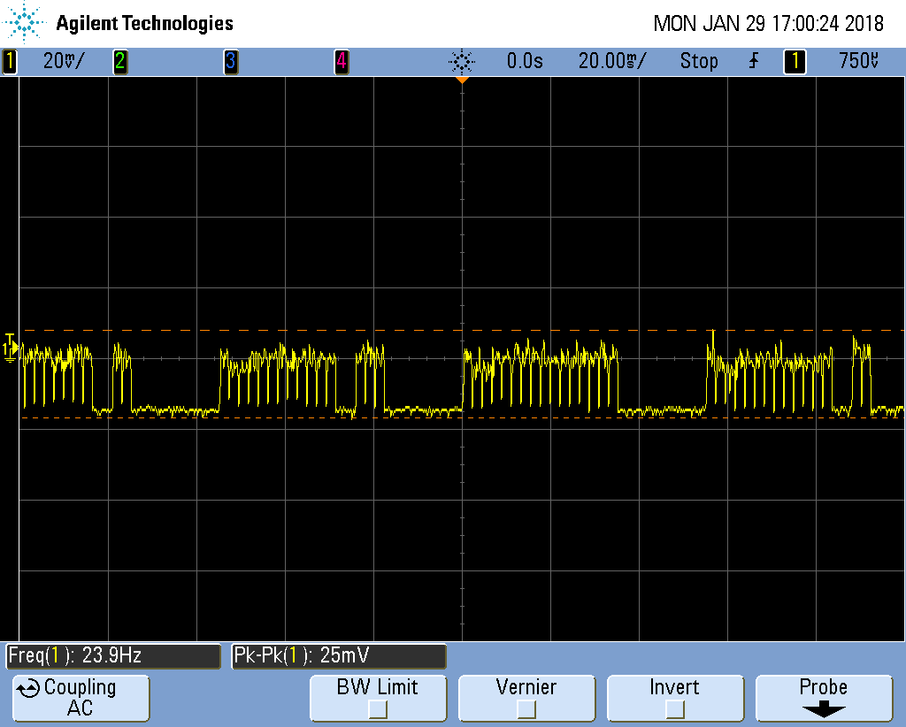
We have a design that needs 5V, 3.3V and 1.2V at big (unknown) currents. I selected the TPS563201 because it is more efficient at low currents than the TPS563208. We never experience low current conditions so I now think I made the wrong choice. We have 8 processors, 4 cameras, WiFi and some sensitive analogue circuits on the PCB. Power supply noise on the 3.3V rail seems to be causing problems. With the system in reset, the 3.3V noise is low level noise. When the code is running, we get 20mVpp noise (see below). Note the horizontal time scale is 20mSec/division. I suspect the WiFi is demanding lumpy currents and causing dips in the voltage. In the data sheet, figures 20 & 21 show the output dip versus current. Maybe we are seeing the low end of the TPS563201 in action.

Is this a correct analysis of this noise?

I think that I will purchase some TPS563208 parts and fit them to see if they are better or worse.

Regards,    Tim Orr

  • Tim,
    For TPS563201, Vpp 20mV makes sense.
    If you need small Vpp ripple, You are right that select TPS563208.
  • Hi Jason,

    I have no idea how to locate my original question, so I am here!

    I swapped the TPS563201 with a TPS563208. There was observable difference. The supply pulses are initiated by the WiFi module. With it de-powered there are no pulses to be seen. With the WiFi powered up and not connected to a target there are occasional pulses. With the WiFi talking to a target and sending video packages, the supply noise looks a bit like video frames. Below is the WiFi trying to connect (using TPS563208). There is a short, apparently solid pulse.

    Increasing the time base reveals a lot of activity in the 2mS burst.

    I can monitor the total current flow into the board with a 2mOhm resistor and I could not see much in the way of correlation. The signal levels are very small. I had to use an external 40dB amplifier. 

    On the PCB, I have routed the boost circuit path (pin 6 - capacitor - pin 2) under the chip. The data sheet avoids this route. The TI document SLVA 818 uses it all the time.

    Is there a problem with my PCB route?

    I think that the IC should not have such a big disturbance in the 3.3V rail. What can I do?

    Regards,  Tim Orr

  • Hi Tim,

    Is the yellow channel showing the Vout ripple at 3.3V rail? It looks like the load is changing abruptly and periodically. Could you please check on the waveform of SW, Vout and Iout( or inductor current) so we could know how the load behaves. Thanks!