This thread has been locked.

If you have a related question, please click the "Ask a related question" button in the top right corner. The newly created question will be automatically linked to this question.

TPS23754: The circuit with current PoE + (TPS23754PWP) is not working properly.

Part Number: TPS23754

Hi,

one of my customer is willing to use TI's PoE TPS23754 for their inderstial PDA application.

A few weeks ago I asked for schematic review and received an answer that nothing catches TI's eyes.

https://e2e.ti.com/support/power_management/power_interface/f/204/p/654757/2408334#2408334

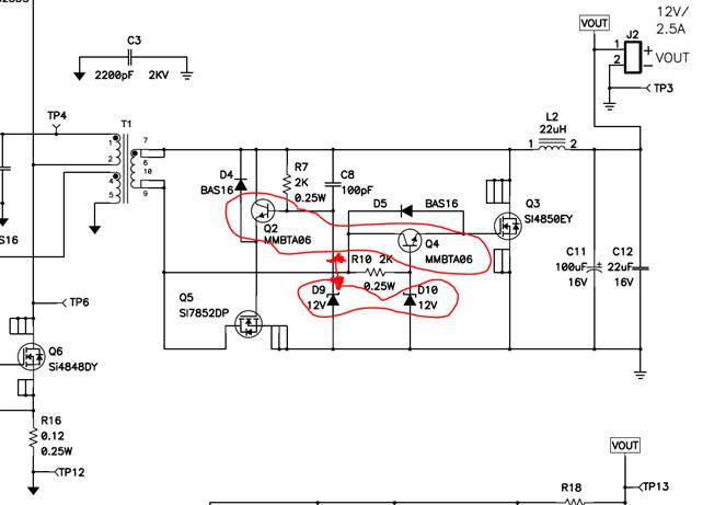
But, the schematic with current PoE + (TPS23754PWP) is not working properly.

- Output swings from 4.7V to 6V with VCC_POE_B (12V in normal operation)
- Q27 ;; SI4848DY (FET) Heat is very severe (soaked to 105 ℃, normal EVM is about 40 ℃)
- Q27 (FET) gate's duty is narrower
- VC shaking with a triangle wave
- Output to VCC_POE_B turns off after a few minutes and turns back on. (reset)
- Existing circuit is normal.
(Even if they remove D41 which gives power to existing circuit, PoE + power output still does not work properly)

Please review the attached files below and give us your feedback.

7080.BB_PoE+Schematic__180110.pdf

POE 파형.zip

thanks,

TS

thanks,

TS

  • Hi,

    I'd like to attach the newest schematic as below.

    Please review this file and give us your opinion.

    SCHEMATIC1 _ 06. PoE+ (30W).pdf

    thanks,

    TS

  • Hi TS,

    The schematic still looks okay to me. This leads me to believe that there is something connected wrong on the board or the wrong populated component value. Are you testing with a PSE? Or a power supply? If a PSE, then the fact that the PSE turns on means the PD controller side design may be okay and the issue is on the converter side. The fault condition of the VC pin dropping is indicative of a short or high loading condition where the PWM controller is in hiccup. You may check that your FETs are still working or if there is a short on your board.

    What will help, since this is a copy of the EVM, that you have the EVM and your board side by side and measure the impedances on both boards at each node. This typically helps find where the issue may be if you find different impedances from the EVM.

    Regards,

    Darwin

  • Hi Darwin,

    thanks for your comments.

    (1) PoE+ debugging completed. Verify normal operation
    - Q2 / Q4 and D9 / D10 are mounted opposite to each other
    - SMT 3rd party incorrectly mounts same SOT-23 material

    (2) Many PCBs are dead during debugging. Where is the most commonly dying point?
    - PCBA already handed does not work even if the same specification (Q2 / Q4 and D9 / D10 exchange each other) is applied.
    A) 12V output appears on Vout, but Q6 FET heat is very severe (250 ℃)
    B) Still VC and Vout output fluctuate
    - To repair, please let me know the dead point to each case.

    thanks,

    TS

  • Hi TS,

    I recommend replacing the FETs and BJTs (both primary and secondary switches).

    Then I would check operation. If it is having the same behavior, I would replace the PD controller.

    Then I would check operation. If it is having the same behavior, I would again check the impedances and compare with the EVM. The difference in impedances for the same nodes can narrow down if a component is damaged or shorted.