This thread has been locked.

If you have a related question, please click the "Ask a related question" button in the top right corner. The newly created question will be automatically linked to this question.

BQ76930: CAP2 does not reach 3,3V Boot-problem

Part Number: BQ76930
Other Parts Discussed in Thread: , TIDA-00449

Hi,

we built up our own hardware using the bq76930.

We have a problem with booting the bq. Cap2 does not reach 3,3V it stays at 200mW.  Cap1 reaches 3,3V fine.

When booting we enter Normal mode but get a xReady internal Failure.

In this state the voltages are:

Vc5x to cap 2  (measured on cap2) is 120mV sth

Vc5X to GND 11,6V

Cap2 to GND 11,58V

Vc5 to GND 11,57V

We can get it running, when we shortly connect the VC5X to CE2.. we have no idea why but this works. Suddenly the Cap2 reaches 3,3V.  It only works when we do this!!

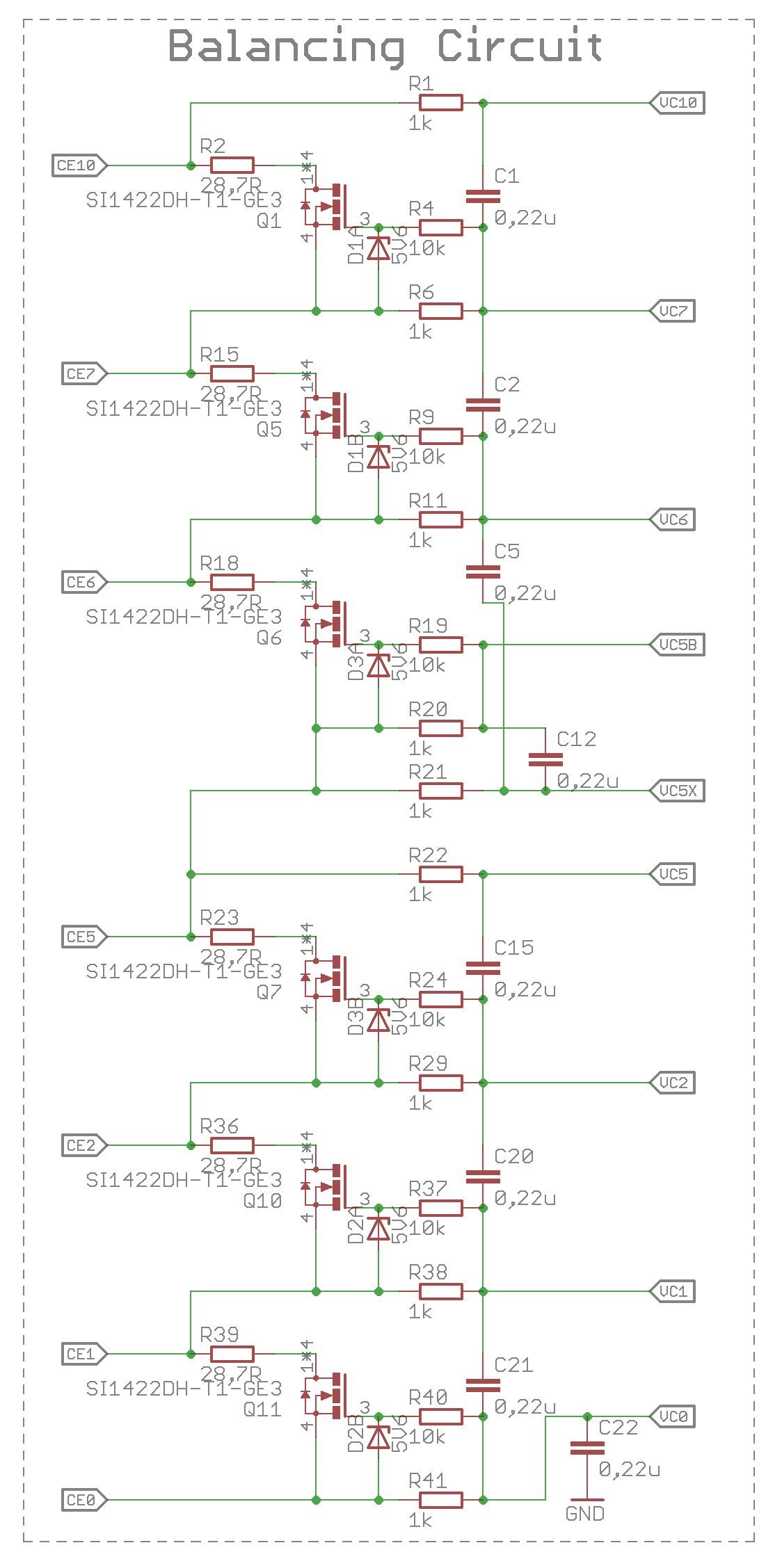
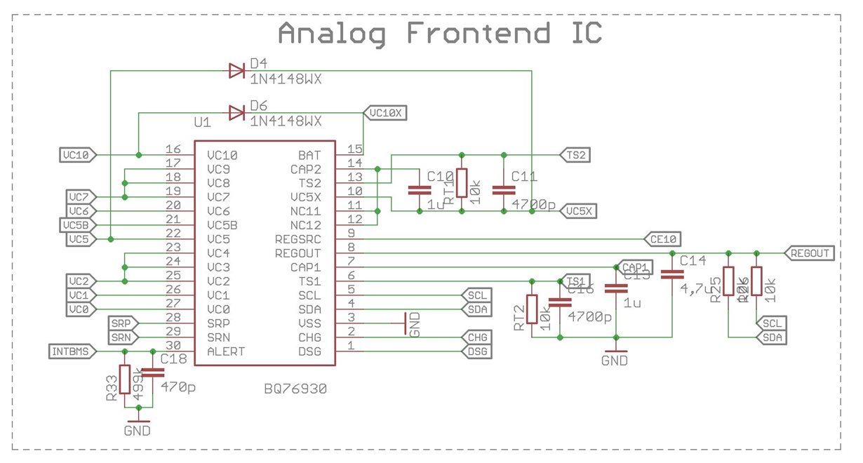
Following attached you can find how we connected the cells to the bq.

We already tried to use bleeding resistor with 1mOhm on Cap1 and Cap2 but this didn't change anything.

I hope anybody can help us.

Best Regards and thanks in advance :)

Sebastian

  • Hi Sebastian,
    In the schematic segments I don't see a couple things needed for operation, they might be there, but please check:
    The BAT pin must have a power input filter resistor, typically 1k from the CE10 to VC10X nets. If the resistor is missing the BAT pin should get a voltage R1 and D6 to operate although improperly so this might not prevent CAP2 from coming up.
    The power filter capacitors are not shown in the schematic segments. There must be a capacitor from VC5X to GND and one from VC10X to VC5X, typically about 10 uF. Without the power filter caps the part may not work properly.
    REGSRC is shown connecting directly to CE10. A filter should be used (resistor & capacitor), but that should not prevent CAP2 from starting.
    It is preferred to have the bottom of C21 connect to GND rather than VC0, see figure 8-2 of the data sheet, but that should not prevent CAP2 from starting.
    Be sure RT1 is in place. A voltage across C11 or RT1 will prevent CAP2 from starting. Also I see the net label on TS2, be sure this does not go somewhere in the circuit which is pulling the net toward VSS, that will also prevent CAP2 from starting. Your pull of VC5X to CE2 may be dropping VC5X with respect to TS2 allowing the part to start. Measure the voltage across TS2 with respect to VC5X before booting. It should be approximately 0V. If it is positive or negative it may prevent CAP2 from starting.
  • Hi WM5295,
    thank you very much for answering! We are still doing some measurements.
    Additionally we discovered another fun fact: when we charge the cells up to 4V (Insteat of 3.45V) booting works totally fine. We don't get any xReady error. But when we start Balancing we get an xReady error.
    We assume that there is some potential mismatch on either Vc10x, VC5x or Cap2? I think that balancing stops because the second adc/balancer group turns off again.

    Is there a reference design where we can see your recommended filters ? We could not find that anywhere. Especially the 10µF Caps. When we see the shematic its easier for us to understand how the curcuit works ;)
    Our hardware was design up on a TI - reference design.

    I already got some measurements:

    According Bat Pin:
    Voltage on Pin Bat to GND = 23,4V
    Voltage on D6+R1 to GND = 23,75V

    Seems like there is not enough voltage to drive a current through the diode?


    According C11 and RT1:
    Voltage on C11 = 0V
    Votlage on RT =0V
    Voltage on Ts2 to VSS=12,2V
    ---> i see ni probleme here..right?

    Thank you for your help !

    Best Regards

    Sebastian
  • Hi Sebastian,
    The standard schematic in simple form is in the bq76930 data sheet figure 8-2, notice the Cf caps toward the right side. Of course the data sheet schematic is simplified and the EVM schematic is more complete, see in the bq76930EVM user guide, slvu925 figures 27 and 28. It is easy to miss the Cf capacitors C34 and C35 in figure 28 amid the evaluation features and population options. The TIDA-00449 has the Cf components on the right of its schematic page 2. The application note bq769x0 BMS Configurations for Cordless Appliances available in the product folder also shows Cf caps with 6 cells, (figure 3) but not with external balancing. A couple of these have the non-preferred VC1 capacitor connection noted before.

    The voltage difference between BAT pin and VC10 seems to indicate the part is missing the Rf resistor for BAT. It must be the voltage VBAT voltage (BAT - VC5X) for the upper group is collapsing during the boot attempt at lower cell voltages below the VPORA level.
    I would guess while it is running and you begin balancing the BAT-VC5X drops into the VSHUT region resulting in the upper group shutting down and the XREADY fault.
    The part needs its power connections and decoupling to work properly.
  • Hi WM5295,
    i see i see. Oh my god we have totally overseen this part. How could this happen in two eye principle :D.
    Thank you very much! We could have seen this on our own, sorry if we stole your time.
    We will do a redesign and report in about a week.
    Thanks again!
    Best regards
    Sebastian