This thread has been locked.

If you have a related question, please click the "Ask a related question" button in the top right corner. The newly created question will be automatically linked to this question.

BQ25895: radiation test

Part Number: BQ25895
Other Parts Discussed in Thread: LM3488,

Hi

Currently my client is configuring circuit with bq25895 + lm3488.

Now we are going beyond the reference value as shown in the drawing at the 240MHz band during the radiation test.
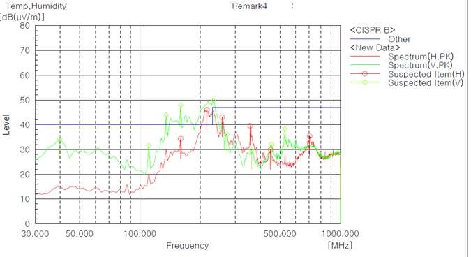

I removed the lm3488, but the same problem occurred.

However, when the output cap of bq25895 was removed, the radiation test was improved.

The cap is required to operate the lm3488. Can we improve otherwise?


It will deliver its pcb and schematic files.

charger895_audio_ver0-2.pdf3603.TOP.PDFL3.pdfL2.pdf8322.BOT.PDF

  • Hi Andy,

    I don't understand why removing a capacitor from SYS would improve noise.  I would expect the opposite.

    The PCB layer pdf's are a bit difficult to read but I found the charger.  I don't see any vias so I have the following concerns:

    1. Is the charger power pad connected to the bottom layer ground with vias?

    2. Are the top layer GND pins tied to PMID capacitor ground by vias through internal layer or bottom layer?  Proper PMID capacitor placement, including ground return path, is usually most critical when trying to minimize noise.   Attached is a presentation explaining optimal layout for minimal noise. 

    Before you re-layout the PCB and if your are not using OTG, I recommend replacing the 2 10uF capacitors closest to PMID with 0.01uF and 0.1uF or 0.1uF and 1uF capacitors.  These decoupling capacitors may reduce the EMI. 

    Also, if you are not use OTG mode, you do not need diode D2.5238.bq2589xbq2419x_29xlayoutandEMIrecommendation.pdf