Hi All,
I have designed a 4-layer (2 oz. copper) PCB using the TSP92641 to drive a single white LED at up to 20A. The design is more or less a copy of the reference circuit 20A EVM schematic. The board runs from a 13.8V, 20A supply and the LED's forward voltage ranges from 2.8 to 3.6V. The IADJ pin is driven from a 2-pole filtered PWM output. The filters have a nominal 160 Hz cut-off. The SDIM input is driven by a second (unfiltered) PWM ouptut.
During testing I've discovered that the LED light output is not very linear with the IADJ voltage. In fact, simply enabling SDIM with IADJ set to its minimum output produces about 600 mA of LED current which represents about 12% of the LED's full-scale output. In an effort to "linearize" this jump, I am attempting to use the SDIM input. At very high duty-cycles (SDIM high >90% of the time), the driver behaves as expected and does indeed dim the LED proportionally. However, as the duty-cycle drops to the 80% level (and lower), the LED noticeably (and randomly) flickers. The "SW" output (TP6 on the application schematic) shows varying numbers of positive pulses which explain the flicker.
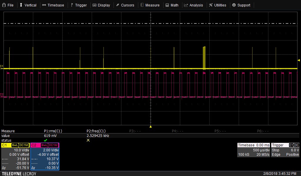
I've attached my schematic (2 pages), a scope trace shown SW (yellow) and SDIM (red) and a graph of the LED output (measured with an external photodiode) versus PWM drive duty-cycle.
Any thoughts much appreciated.
Thanks,
Scott