This thread has been locked.

If you have a related question, please click the "Ask a related question" button in the top right corner. The newly created question will be automatically linked to this question.

TPS61096A: TPS61096A: stange behaviour in our application

Part Number: TPS61096A
Other Parts Discussed in Thread: TLV61046A

Hi,

Sorry to bother, but we face some strange issue in our TPS61096A  based design. We have recently got out of production few boards in which we attempt to use TPS61096A to generate stable 24V from 3.6V supplied by Li-Ion battery. Unfortunately, the voltage on the output of TPS61096A  is far from 24V.  Specifically, the three boards we have tested so far have on their outputs 3, 5 and 6.7 V, respectively.

The schematic of the application circuit we have is as follows:

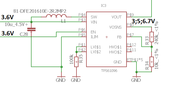
On the output we currently have a 10uF capasitor and 1.1 MOhm resistor.

Based on few quick test of one board I observe the following voltage (using a multimeter):

1. when EN is pulled down there is about 3V on TPS61096A  Vout 

2. when EN is pulled up there is 6.67V on TPS61096A  Vout. Vosns is also 6.67V. In the middle of the voltage divider voltage is about 0.27V. Also I have noticed that the other side of the PCB, connected to the thermal PADs via through holes, starts to heat up. 

Any ideas of what is wrong with our design?

  • could you share your layout? this issue seem to be caused by the location and routing of the COUT.
  • Dear Jasper,

    Sure, here it is. The output line is highlighted. 

    Indeed, the output capasitor is decently far away. Actually, in parallel to Cout we also have two 402 capasitors (100n & 33p), but they are placed even further.

    If needed, we can install another capasitor closer to the Vout line. Do you think this might help? Also the size of the surface area is decently small. The reason after this is that we will hardly need more than 10 mA output current in our design. 

    I have also made some measurements of the circuit consumption - it consumes about 250 mA, which is the set current limit in our case. For me this looks like the DC-DC concerter does its best, but by some reason cannot pull the voltage up above particular level.

  • yes. you need to place a 0402 capacitor between the VOUT and GND pin of the IC. for you current requirement, the ILIMIT pin should be high, but it also closed the current limit of this device.
    why not TLV61046A, which seem to be better for your application.
  • Dear Jasper,

    We have tried adding another capasitor - it did not work. Do you have any other ideas?

    Can you explain, why does the DC-DC converter, having 1.1 MOhm output load (24V*24V*1.1MOhm<1 mW), sucks as much as 0.25A (0.25A*3.6V=0.9W)? And how does this match the efficiency charts of the DC-DC converter? As for increasing the current limit - frankly speaking I have some doubts that this will help. 

  • is the device damaged? please measure the impendance between each pin and the GND pin.
    could you apply an EVM for reference. by measure the performance in EVM, and exchange the IC in EVM and system board. we can locate the issue.
  • I am not sure. As you can see from the first post - some functions seem to be correct. Also we have tested it with 3 boards, thus individual issues are not very likely.

    Here are the impedance readings from the multimeter (pin name, pin number, impedance)

    LV1, 1, 100 kOhm
    LV2, 2, 100 kOhm
    VIN, 3, 88 Ohm
    SW, 4, 88 Ohm
    ILIM, 5, 0 Ohm
    EN, 6, 62 kOhm
    FB, 7, 10 kOhm
    VOSNS, 8, 250 kOhm
    VOUT, 9, 3 MOhm
    GND, 10, 0 Ohm
    HVO2, 11, no value 
    HVO1, 12, no value 

    Does it give any hints?

    As for the EVM - we do not have a dev kit. Also soldering IC manually, given the specifics of its package, may be somewhat tricky. Maybe I can try this tomorrow, if nothing else comes up.

  • the resistance of the SW and VIN is too low. remove the inductor and check which. pin cause the issue.