This thread has been locked.

If you have a related question, please click the "Ask a related question" button in the top right corner. The newly created question will be automatically linked to this question.

TINA/Spice/UCC28950: Parallelable power-supply module using UCC28950 Phase-Shift Full Bridge Controller and UCC29002 (PMP8740 module)

Part Number: UCC28950
Other Parts Discussed in Thread: TINA-TI, , UCC29002, PMP8740

Tool/software: TINA-TI or Spice Models

Support Path: /Product/Find help on educational technology and calculators/

Hi,

I must developp a power supply system with the following electrical characteristics :

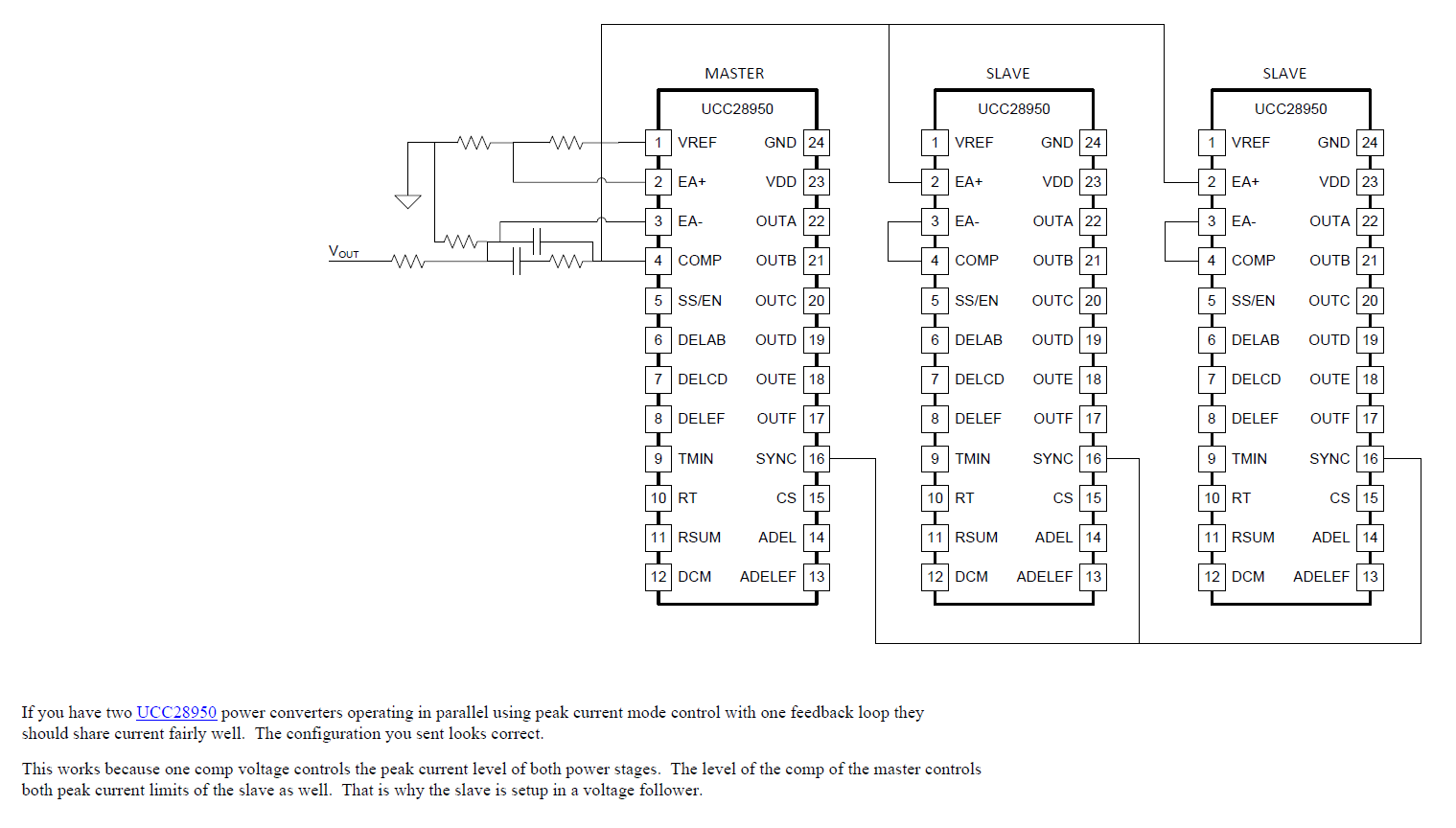
- 3 parallele power supply modules in order to provide more electrical power

- each module use "ZVS Phase-Shifted Full-Bridge converter" topology based on UCC28950 controller with synchronuous rectifier.

- on each module use an UCC29002 to share current between the 3 power supply module.

This architecture looks like the PMP8740 developped by TI (refer to slup349 document).

I have several questions about PMP8740 power supply module :


1. design justification document :

Have you got a design justification document (besides to slup348 and slup349 document) ?


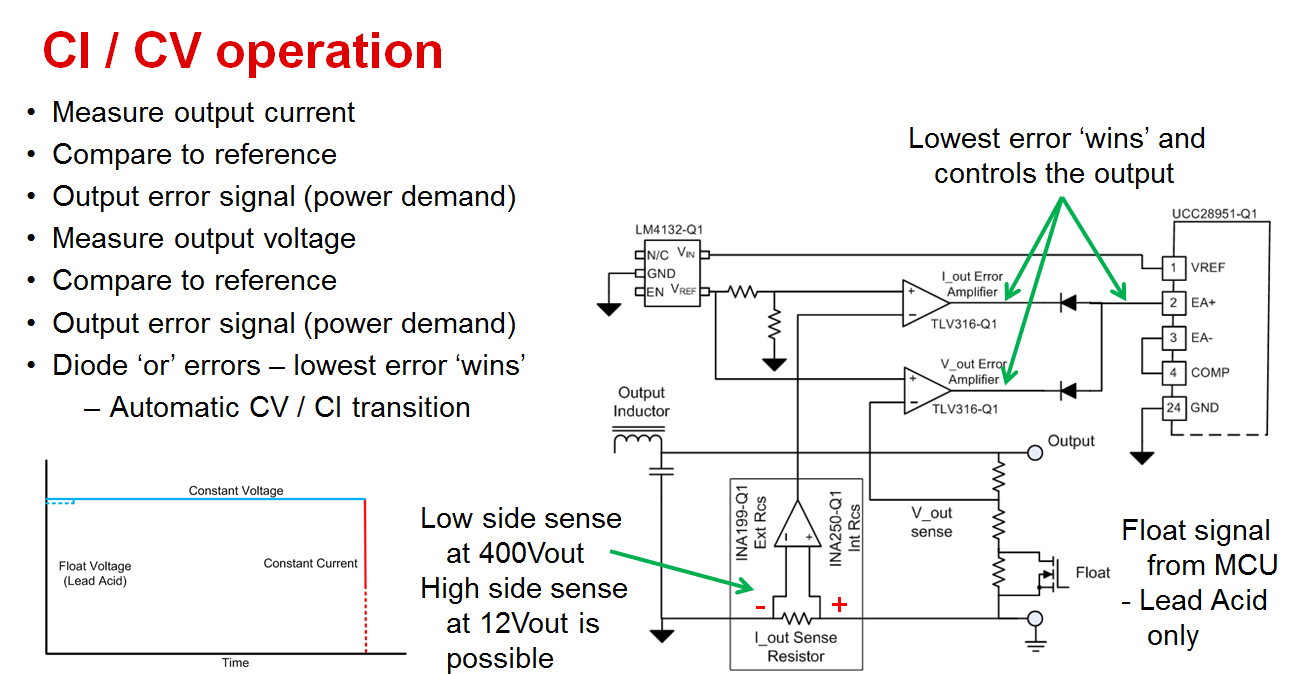
2. voltage feedback :

.

I don't want realize a current loop, voltage loop is enough for my application.

Into voltage loop, why IOUT (power supply output current) is used into this voltage feedback ?

Bests Regars

Benoit PINARD

  • Hi Benoit

    1/ I don't have any documentation other than that which is on the PMP8740 site - sorry

    2/ The feedback network is a classic feedback implementation to achieve a constant voltage / constant current output characteristic. If you don't need CI operation then simply remove D3 in your schematic and all of the components feeding it. Assuming that you are monitoring the PSFB input current, you will still have current limiting at the output - but the current being limited is the INPUT current and the proportionality between Iin and Iout will depend on both Vin and Vout - so it is current limiting but with larger variations in the actual output current limit point than you get with the CV/CI circuit. The CV/CI circuit of course also needs input current monitoring to effect peak current mode - you can see this in the diagram on slide 7-21 of the document slup349

    If you use the UCC29002 load share controller you will have to add a Vout sensing function to the PSFB output and the resulting system will be 'democratic' in the sense that no one power module is a master.

    If you are willing to use a master / slave arrangement then you won't need a separate load share controller and can configure the three UCC28950 devices in parallel as shown below. the master has control of the loop and the current demand signal at the output of its error amplifier is fed to the slave units. of course if the master fails, then the whole system stops operating.

    Regards

    Colin

  • Hi Colin,

    Thank you for your response but i think that my question 2 wasn't clear.

    Into electrical schematic of PMP8740 module :

    Into voltage loop (for voltage control mode), why IOUT (power supply output current) is used into this compensation circuit via R4 resistor=> refer to attached files.

    Into PMP8740 module, Input current is sensed by current transformer and send to CS pin.

    Bests Regards

    Benoit PINARD

  • Hi Benoit - I misunderstood your question for sure. I'm checking with some colleagues and will post a reply when I receive it.
    Regards
    Colin
  • Hi Benoit - I got this reply from the designer of the PMP8740

    'R4 create a sort of “positive” output impedance and let Vout droop a bit vs. Iout. This method helps stabilizing the parallel between modules, when the battery impedance is very low.

    It’s not easy to calculate it, because lot of parameters must be known, so I put this value as starting point. Nevertheless, I had no problem to parallel at least two modules.'

    To summarise, The IOUT feed into the voltage amplifier degrades the load regulation. If you are using the UCC29002 load share controller, or if you are going to use the master / slave current sharing idea that I sketched above then you won't need to use the IOUT signal to degrade the load regulation and R4 can be deleted. (or left as a 'do not populate' placeholder. I think this answers your question but if now please don't hesitate to let me know

    Regards

    Colin

  • Thank you very much. It is perfect.

    Regards

    Benoit