This thread has been locked.

If you have a related question, please click the "Ask a related question" button in the top right corner. The newly created question will be automatically linked to this question.

TPS61220: TPS61220 with 6.0V or higher output

Part Number: TPS61220
Other Parts Discussed in Thread: TPS61252, LMV431

Hi,

I am searching for boost (or similar device) that can produce from 6.0V to 7.0V at around 100mA for MSP430x2xx fuse blow. I want also overvoltage protection, that during any fail,output doesn't go over 7.0V.

Somehow, TPS61220 is close to this. However, per datasheet max output voltage is 6.0V, and overvoltage protection threshold is 6.0 to 7.5V. Is it possible to use this device with 6.5V (or 6.3V, or 6.0V) output? Is there a similar device from TI that can produce 6.5V on output, but with internal output voltage protection close to 7V?

EDIT: There are plenty of graphs inside TPS61220 device datasheet, but I didn't found one with over voltage protection in action. If overvoltage protection will fix voltage to 6.5V (and not allowing to go higer, ever) and device can operate with activated overvoltage protection normaly, I am fine with this.


Regards,

Josip

  • The engineer supporting this device is currently out of office. For the time being, let me answer some of your questions. The output voltage is monitored internally (not shown in the datasheet block diagram, but mentioned in Section 10.3.6). Because of the variations in over-voltage protection threshold, it is not guaranteed to operate with Vout set above 6.0V. Regarding other devices, you may need to wait until the engineer is back to office. Anyway, thank you for considering our device in your application
  • thanks Youhao.
    the tps61220 is the closest device to your requirements. the. output voltage can set to
    no higher than 6V. there is no better solution.
  • And what will be if output voltage is set to 6.2V? Can I see any graph with output over voltage protection activated? What will be device output voltage value during active protection period?
  • i'm out of office and can't measure the waveform. normally the device will stop switching and VOUT drops. the device start switching again if VOUT is 100ma (maybe) lower than the setting voltage ,
  • Note that OVP circuit directly monitors Vout. With the resistor divider at the FB pin to set the Vout>6.0V, you face the risk of hitting the OVP. To be safe, you need to set your Vout always <6.0V, including tolerance, to avoid falsely trip OVP.

    You may consider another option: use our other part like TPS61252 that can produce >6V and add an LMV431 to implement the OVP function: monitoring Vout and use the LMV431 to pull down the EN to shutdown.
  • Jasper Li said:
    i'm out of office and can't measure the waveform. normally the device will stop switching and VOUT drops. the device start switching again if VOUT is 100ma (maybe) lower than the setting voltage ,

    I am not in hurry, I will wait for waveform.

    Youhao Xi said:
    Note that OVP circuit directly monitors Vout. With the resistor divider at the FB pin to set the Vout>6.0V, you face the risk of hitting the OVP. To be safe, you need to set your Vout always <6.0V, including tolerance, to avoid falsely trip OVP.

    I just want to see waveform with OVP activation / deactivation to clear my doubts and close the topic. I just need to TPS61220 generate 1ms spike little over 6.0V from 5V input, for blowing fuse. Is in this short period of time, output voltage regulation working nicely or terrible (tripping OVP), for my case is irrelevant.

    Jasper Li said:
    You may consider another option: use our other part like TPS61252 that can produce >6V and add an LMV431 to implement the OVP function: monitoring Vout and use the LMV431to pull down the EN to shutdown.

    Thank you for pointing me to this option, but I prefer to have solution, simple as possible (low number of components and small PCB space).

  • as i mentioned, the device stop switching when trigger OVP and start switching again if the voltage drops to lower than the OVP.
    however, as the delay of the OVP circuit, the output will varies from the load condition and the input voltage. we can't guarantee the voltage doesn't go over 7V.

    i agree with Youhao, you need to an additional IC or similar circuit to achieve the OVP function.
  • Is it possible to see scope waveform for this device, with OVP triggering. Ideal case should be for 100mA, with 5V input and output set to 6.5V. To see how after enabling voltage rising close to 6.5V and OVP triggering in action. If this is not possible, than waveform for OVP triggering for similar device. If this already exist in any similar device datasheet, please point me.
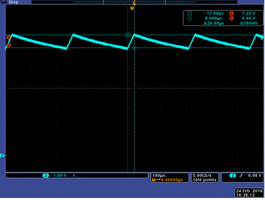
  • here is the OVP waveform of TPS61220 but different input and load condition. the OVP value varies from different VIN, load and device. so i would not suggest setting VOUT higher than 6V, 

  • I am not sure if I am looking this graph on the right way. Can you just clarify points, with max 7.2V and minimum 6.5V value (related values to this waveform, not in general). Is this graph related to device that is (normally) switching (voltage rise) up to 7.2V, and than OVP turns off switching until voltage drop down to 6.5V. And it is repeated again. Or on graph is something else?

  • your understanding is correct.