This thread has been locked.

If you have a related question, please click the "Ask a related question" button in the top right corner. The newly created question will be automatically linked to this question.

UCD924x Turn-on and Stay-on Dependancy Timing

Other Parts Discussed in Thread: UCD9224, UCD9244

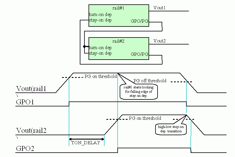
Please describe the timing associated with the controller evaluating the stay-on dependencies. I would like to understand when the controller starts evaluating the stay-on dependencies. They somehow must be ignored during turn-on, and at some time after “regulating” they are probably evaluated. Please elaborate.

  • Mark,
    Below is a description of how the sequencing input and output signal operate in the UCD92xx devices.

    PowerGood and other Sequencing Output Signals
    First, lets defined what the controller means by "Regulating".  An I/O pin (GPO) configured to be a sequence output goes active when the output voltage crosses the configurable PowerGood threshold for that rail.  You can make the GPO come active sooner by reducing the POWER_GOOD_OFF and POWER_GOOD_ON thresholds.

    For a I/O pins configured to be a sequence GPO, setting it to go active with all rails above their PowerGood threshold is essentially identical to the default PowerGood pin function.  In fact, the Power Good Pin can be reconfigured to be a sequence GPI or GPO as well.  Internally, the PowerGood pin is the same digital I/O as all the other configurable pins; that is, it is set by the firmware. 

    Turn-on and Stay-on Dependency Signals
    The turn-on and stay-on dependency signals (either internal or external) are poled in the firmware, which looks for a state change in each signal.  This poling occurs every 70 to 300 usec.  So for pins defined as a turn-on dependency, the controller looks for a low-high transition.  For pins defined as a stay-on dependency, the controller looks for a high-low transition.  This is the mechanism the controller uses to "ignore" the stay-on dependency during the soft start ramp. 

    For example, if it is desired for an application to shut down all the voltage rails if one rail experiences a fault, and there are three UCD92xx devices, each controlling 4 voltage rails (12 voltages total), we should do the following:.  Two I/O are chosen on each controller and configured as Stay-on dependant inputs.  Then the PowerGood signal from controller#1 is fed to the stay-on input for controller#2 and controller#3;  the PowerGood signal from controller#2 is fed to the stay-on input for controller#1 and controller#3; and the PowerGood signal from controller#3 is fed to the stay-on input for controller#1 and controller#2.

    Fault Events
    A fault, such as an over voltage or over-temperature fault, will cause the control signals for that regulated voltage to shut down as soon as the fault is detected. (Given the configured fault response code as defined by the PMBus standard.)  However, the GPO signals will not turn off until the output voltage goes below the configured PowerGood threshold. 

    Note that there is an code bug (errata) on the operation of the "Continue for xx msec" fault response in the UCD9224/46/48 devices.  What the device should do is start a timer when the fault first occurs, then at the end of the continue time, if the output is back in regulation, no fault should be posted.  What actually happens is that the counter is started at the first instance of the fault, but the device shuts down and posts the fault at the end of the continue time regardless if the system recovered or not.  This behavior has been fixed in newer devices like the UCD9212 and UCD9244.

    Below is an example for a case with two controllers, the second controller is dependant on the first controller to start and both controllers will shut down if one of the voltage rails experiences a fault. 


    I hope this helps.