This thread has been locked.

If you have a related question, please click the "Ask a related question" button in the top right corner. The newly created question will be automatically linked to this question.

UCC28704: Short circuit response

Part Number: UCC28704

Hello,

I wanted to understand UCC28704’s short circuit response. Is my understand of events below correct?

  1. Short circuit
  2. UCC28704 operates in cycle by cycle current limit for 120ms (tblank of CCUV)
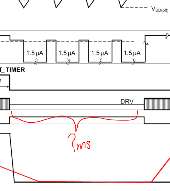
  3. UCC28704 enters 3 cycles of VDD_UVLO
  4. Restarts at the power up of the 4th cycle and restarts step 2 if fault persists.

If correct, can you help me understand how long those 3 VDD_UVLO cycles take?

Thanks,

Rohit Joshi

  • Each cycle of the three cycles is identical in theory. The time of each cycle includes charging time t_chg (VDD rise) and discharging time t_disc (VDD decrease).

    1) The charging current in t_chg can be estimated by average as I_chg = (Vbulk-14.4V)/Rstr, then

    t_chg = Cdd * [VDD(on) - VDD(off)] / (I_chg - 1.5uA) = Cdd * (21V - 7.7V) / (I_chg - 1.5uA)

    Rstr is the resistor connected betwen VDD and the bulk capacitor, and refer to page 18 of UCC28704 ds, Figure 19 (RSTR).

    2) The discharging current in t_disc is the difference between UCC28704 VDD discharging current (about 2mA) and current I_chg. then

    t_disc = Cdd * [VDD(on) - VDD(off)] / (2mA - I_chg) = Cdd * (21V - 7.7V) / (2mA - I_chg)

    So the three cycle total time = 3 * (t_chg + t_disc)

    Example:

    Vin = 90Vac, so Vbulk = 1.414 * 90V = 127.3V, Cdd = 0.33uF, Rst = 15.3 M-ohm 

    I_chg = (Vbulk-14.4V)/Rstr = (127.3V - 14.4V)/15.3M = 7.38 uA

    t_chg = Cdd * (21V - 7.7V) / (I_chg - 1.5uA) = 0.33uF * 13.3V / (7.38uA - 1.5uA) =  0.7464 s

    t_disc = Cdd * (21V - 7.7V) / (2mA - I_chg) = 0.33uF * 13.3V / (2000uA - 7.38uA) =  0.0022 s

    Then the time of three cycles is estimated as:

    3 * (t_chg + t_disc) = 3 * (0.7464s + 0.0022s) = 2.2458 s

    The total off time is roughly about 3 cycle + t_chg = 2.2458s + 0.7464s = 2.9922 s as a typical esitamation at 85Vac input.

    At different input voltage, the total off time will vary due to different I_chg. Also VDD(on), VDD(off), 1.5uA, and 2mA, are varying from part to part so the above estimation is based on typical numbers in the ds.

  • Hey Rohit,

    The time for those cycles is dependent on the VDD capacitors charging and discharging. Therefore, we can calculate the time going from VDDoff to VDDon and vice versa by using the equation for a capacitor I = C dV/dt. Isolating dt leads to dt = C/I * dV.

    The bias current consumption during a fault becomes IFAULT, and dV = VDDon - VDDoff. The remaining variable is Capacitance, which is dependent on the design. In the figure you posted, this would be when the VDD drops from VDDon to VDDoff.

    When VDD voltage hits VDDoff, the bias current changes to ISTART and starts to to charge the VDD capacitor until the VDD level rises above the VDDon threshold.

    Adding up the VDD charging and discharging times will result in the total time it takes to go through the fault cycle.

    I hope this helps!

    Regards,
    Davit