This thread has been locked.

If you have a related question, please click the "Ask a related question" button in the top right corner. The newly created question will be automatically linked to this question.

bq25600: Charger starts draining excessive power (~100mA) instead of charging the battery

Part Number: BQ25600

Hello everyone,

We have designed a PCB which uses a bq25600 as the charger for the Lithium Ion system battery. In approximately 30% of the devices, we encounter an issue where the bq25600 starts consuming 100mA whenever the battery voltage rises above 4.05V. The charger then does not resume normal operation (and keeps consuming power) until the battery voltage falls under 3V.

The system architecture for the power section of our device is the following:

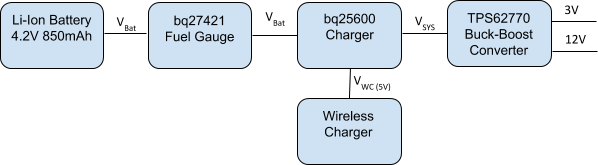
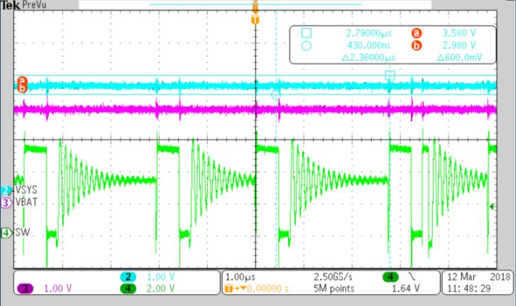
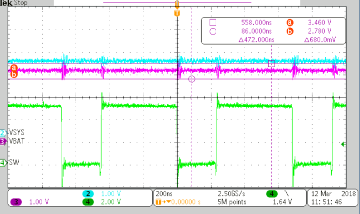
The issue persists even if we replace the battery with a battery simulator and the wireless charger with a conventional power supply. Using a thermal camera, we notice that the bq25600 becomes hotter with respect to its normal behavior.

The bq25600 is configured by a microcontroller as follows:

Minimum system voltage: 3.0 V

Input Current Limit: 500 mA

Charge Current: 240 mA

Precharge Current:120 mA

Termination Current: 120 mA

Regulation/Charge Voltage: 4.242 V

The CE pin is connected to GND and the PSEL pin is connected to Logic High (3V).

Dumping the bq25600 registers, the resulting configuration is:

[bq25600] Reg 0:0x04
[bq25600] Reg 1:0x14
[bq25600] Reg 2:0x82
[bq25600] Reg 3:0x31
[bq25600] Reg 4:0x60
[bq25600] Reg 5:0x8F
[bq25600] Reg 6:0x66
[bq25600] Reg 7:0x4C
[bq25600] Reg 8:0x00
[bq25600] Reg 9:0x00
[bq25600] Reg 10:0x00
[bq25600] Reg 11:0x01

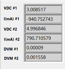
The charger reports the following values during a fault condition:

[bq25600] Reg 0:0x04
[bq25600] Reg 1:0x14
[bq25600] Reg 2:0x82
[bq25600] Reg 3:0x31
[bq25600] Reg 4:0x60
[bq25600] Reg 5:0x8F
[bq25600] Reg 6:0x66
[bq25600] Reg 7:0x4C
[bq25600] Reg 8:0x34   (Power good, not in thermal regulation, not in Vsysmin regulation, FAST Charging, USB Host SDP (500mA))
[bq25600] Reg 9:0x00
[bq25600] Reg 10:0x80 (Vbus attached)
[bq25600] Reg 11:0x01

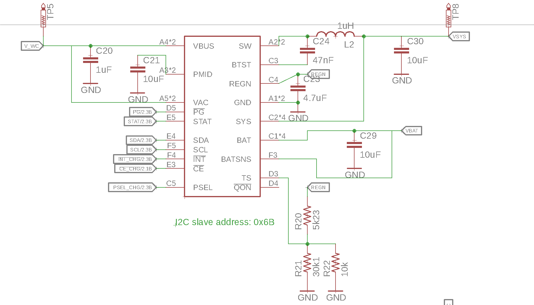
The schematic for the charger is the following:

We would really appreciate any help in solving this issue. Let me know if I can provide any additional information.

Thanks,

Luigi

  • Hey Luigi,

    What is the load current from your buck-boost converter?

    Is the voltage you measured (when this occurs) coming from the cell voltage reading from the gauge, or it is being directly measured at the BAT pin of the charger? If the former, can you measure directly at the BAT pin? This also applies to the exit condition (battery at 3V).

    When testing with a fixed power supply, what were the test conditions? 5V input with what current limit, if any?

    Based on the register data you provided, am I correct in saying that this fault only occurs when you plug in VBUS? It seems that the initial difference between the two register dumps is that VBUS has not been applied and the charger is not charging.

    When you mentioned it is consuming 100mA, are you referring to battery discharge current?

    I see that the /CE pin is being driven elseware. Is there anything in code that may be toggling this pin at different points in time?


    Regards,
    Joel H
  • Hello Joel,

    Joel Hernandez II said:
    What is the load current from your buck-boost converter?

    The average current is 200uA.  There are short bursts up to 5mA during radio transmission.

    Joel Hernandez II said:
    Is the voltage you measured (when this occurs) coming from the cell voltage reading from the gauge, or it is being directly measured at the BAT pin of the charger? If the former, can you measure directly at the BAT pin? This also applies to the exit condition (battery at 3V).

    The voltage is measured directly at the BAT pin of the charger. There is almost no difference between the voltage at the cell and the one at the BAT pin of the bq25600.

    Joel Hernandez II said:
    When testing with a fixed power supply, what were the test conditions? 5V input with what current limit, if any?

    The power supply was connected to the Vbus pin and was providing 5V without any current limiting.

    Joel Hernandez II said:
    Based on the register data you provided, am I correct in saying that this fault only occurs when you plug in VBUS? It seems that the initial difference between the two register dumps is that VBUS has not been applied and the charger is not charging.

    That is correct. If the system is not charging, the power consumption from the charger is negligible.

    Joel Hernandez II said:
    When you mentioned it is consuming 100mA, are you referring to battery discharge current?

    The current is sinked from both the BAT pin (~50mA) and the VBUS pin (~50mA). The charger reports that it is charging the battery when it is effectively discharging it at 50mA.

    Joel Hernandez II said:
    I see that the /CE pin is being driven elsewhere. Is there anything in code that may be toggling this pin at different points in time?

    We have monitored /CE with an oscilloscope and we cannot notice any odd activity on the pin.

    Thanks!

    Luigi

  • Hey Luigi,

    A few comments and questions:

    Luigi Zevola90 said:
    The current is sinked from both the BAT pin (~50mA) and the VBUS pin (~50mA). The charger reports that it is charging the battery when it is effectively discharging it at 50mA.

    Here, are you saying there 50mA is being drawn from the input source at VBUS AND 50mA is being drawn from the battery into the charger? 

    If so, I am inclined to say that there is something pulling current out of another pin. 

    Also, you mentioned that the charger reports the following register values during a fault condition. 

    [bq25600] Reg 0:0x04
    [bq25600] Reg 1:0x14
    [bq25600] Reg 2:0x82
    [bq25600] Reg 3:0x31
    [bq25600] Reg 4:0x60
    [bq25600] Reg 5:0x8F
    [bq25600] Reg 6:0x66
    [bq25600] Reg 7:0x4C
    [bq25600] Reg 8:0x34   (Power good, not in thermal regulation, not in Vsysmin regulation, FAST Charging, USB Host SDP (500mA))
    [bq25600] Reg 9:0x00
    [bq25600] Reg 10:0x80 (Vbus attached)
    [bq25600] Reg 11:0x01

    Can you take a register dump before the fault occurs, but after you apply the input power? 

    I am curious if you can take a waveform of several channels of the charger. If the fault occurs immediately after the applying the input source to VBUS, please capture these nodes during VBUS plug in. If not, does the charger charge the battery for some time before the fault occurs? 

    Channel 1) VBUS - Input voltage

    Channel 2) SW - Switching node

    Channel 3) IBAT - Battery current 

    Channel 4) IBUS - Input current

    Regards,

    Joel H

    Regards,

    Joel H

  • Joel Hernandez II said:
    Here, are you saying there 50mA is being drawn from the input source at VBUS AND 50mA is being drawn from the battery into the charger?

    That seems to be the case.

    Joel Hernandez II said:
    Can you take a register dump before the fault occurs, but after you apply the input power?

    I am curious if you can take a waveform of several channels of the charger. If the fault occurs immediately after the applying the input source to VBUS, please capture these nodes during VBUS plug in. If not, does the charger charge the battery for some time before the fault occurs?

    If Vbat is below 3.9V and Vbus (5V) is applied, the battery is charged as expected until Vbat reaches 4.045V. When Vbat reaches 4.045V, the charger enters the fault condition.

    If Vbat is above 3.9V and Vbus (5V) is applied, the charger starts immediately draining current from both the battery and Vbus. Once the charger enters this fault condition it remains in this mode unless the battery is below 3V. That is, even if Vbus is disconnected, it will still drain ~100mA (entirely from the battery). If Vbus is reconnected, it will start draining again from both Vbat AND Vbus.

    Dumping the registers, we obtain:

    Initial Configuration Idle, Vbat = 4.00 V Connecting Vbus = 5 V, Vbat = 4.00 V Connected Vbus = 5 V, Vbat = 4.00 V
    [BQ25600] Register 0 0x05 0x05 0x04 0x04
    [BQ25600] Register 1 0x14 0x14 0x14 0x14
    [BQ25600] Register 2 0x82 0x82 0x82 0x82
    [BQ25600] Register 3 0x11 0x11 0x11 0x11
    [BQ25600] Register 4 0x60 0x60 0x60 0x60
    [BQ25600] Register 5 0x8F 0x8F 0x8F 0x8F
    [BQ25600] Register 6 0x66 0x66 0x66 0x66
    [BQ25600] Register 7 0x4C 0x4C 0x4C 0x4C
    [BQ25600] Register 8 0x00 0x00 0x34 0x34
    [BQ25600] Register 9 0x00 0x00 0x00 0x00
    [BQ25600] Register 10 0x00 0x00 0x80 0x80
    [BQ25600] Register 11 0x01 0x01 0x01 0x01
    [bq27421] Current - 0 mA 0 mA -53 mA
    [bq27421] Voltage - 4000 mV 4000 mV 4000 mV

    Initial Configuration Idle, Vbat = 3.70V Connected Vbus = 5 V, Vbat=3.70V
    [BQ25600] Register 0 0x05 0x05 0x04
    [BQ25600] Register 1 0x14 0x14 0x14
    [BQ25600] Register 2 0x82 0x82 0x82
    [BQ25600] Register 3 0x11 0x11 0x11
    [BQ25600] Register 4 0x60 0x60 0x60
    [BQ25600] Register 5 0x8F 0x8F 0x8F
    [BQ25600] Register 6 0x66 0x66 0x66
    [BQ25600] Register 7 0x4C 0x4C 0x4C
    [BQ25600] Register 8 0x00 0x00 0x34
    [BQ25600] Register 9 0x00 0x00 0x00
    [BQ25600] Register 10 0x00 0x00 0x80
    [BQ25600] Register 11 0x01 0x01 0x014
    [bq27421] Current - 0 mA 124 mA
    [bq27421] Voltage - 3700 mV 3720 mV

    Please note that the charging current is set to 120mA in this configuration.

    We are using a Keithley 2306 Battery Simulator to replicate various conditions in the system. In our setup, Channel 1 is the battery and Channel 2 is VBus. We are monitoring Vbat and SW with an oscilloscope. Channel 1 of the oscilloscope (Yellow) is Vbat and Channel 2 (Blue) is SW.

    If we connect the charger (enabling channel 2 on the Keithley) when Vbat (channel 1) is 3.2 V, we get:

    We can increase Vbat and the charger continues to operate normally:

    But when we get closer to 4.05V the charger starts draining current from both Vbat and Vbus:

    At Vbat = 4.05 V the charger enters the fault condition:

    And keeps consuming ~100mA even when the charger is disconnected:

    We have also recorded the behavior: 

    Let us know if we can capture any additional signals that can be useful in troubleshooting the issue.

    Thanks again for the help!

    Luigi

  • We are still struggling with this issue. We would really appreciate getting some feedback and pointers towards the right direction.

    Thanks,
    Luigi
  • Hey Luigi,

    Sorry for the late response. I was reviewing your waveforms, register dumps, and test conditions.

    I have a few comments and questions:
    I noticed the measured battery voltage is from the Keithly/Gauge acting as the cell voltage. The gauge also only reports the cell voltage. What is the measured voltage at the BAT pin of the charger (DC)?

    For the battery, are you adding a bulk capacitor? For our validation testing, we add a 100,000uF capacitor to the BAT terminal to mimic the internal cell capacitance. I believe the battery simulators do not model this capacitance, and only acts as a current-sinkable power supply.

    Another note was the charging current with respect to the termination current. They are set to nearly the same value at 120mA. There could be several things occurring here. First, there seems to be a lot of ringing at the BAT pin (if that is where you are measuring), which is likely taking the BAT voltage into or above the CV region of regulation voltage. Again, trying adding a large bulk capacitance here. If the ringing is taking the battery voltage marginally or deep into CV mode while the termination current threshold and the fast charge currently closely coincide, the charger may attempt to terminate prematurely. Additionally, the size of the ringing may be taking the charger between recharge and charge cycles. The recharge threshold is 100mV per your settings. If the charger is going very deep into or above the CV threshold just due to the ringing, it is possible the charger is flowing in and out of the BATOVP protection, forcing it to discharge.

    Another question is how often you are sampling the I2C registers of the charger?

    Here are few things to try:
    1) Add large bulk capacitance in parallel with the BAT pin of the charger or the Keithley.
    2) Measure the DC voltage at the BAT pin of the charger.
    3) Change the Fast Charge Current limit in REG02 to something higher than the termination current.
    4) Change the Charge Regulation Voltage (BATREG) in REG04 to something much higher than 4.240V to push the CV threshold out of the way.
    5) Change either the Fast Charge current to a higher value OR add a load to the SYS pin ~500mA (you will likely have to change the IINDPM limit in REG00 to something higher than 500mA)


    Regards,
    Joel H
  • Hello Joel,

    Thank you for the feedback and advice. A few points on the questions you raised:

    Joel Hernandez II said:
    I noticed the measured battery voltage is from the Keithly/Gauge acting as the cell voltage. The gauge also only reports the cell voltage. What is the measured voltage at the BAT pin of the charger (DC)?

    We have noticed no significant voltage drop between the cell voltage and the BAT pin of the bq25600. The oscilloscope is connected directly (<1mm) to the BAT pin of the bq25600. On all the oscilloscope screenshots, we see no significant deviation from the cell voltage on the Keithley. 

    Joel Hernandez II said:
    For the battery, are you adding a bulk capacitor? For our validation testing, we add a 100,000uF capacitor to the BAT terminal to mimic the internal cell capacitance. I believe the battery simulators do not model this capacitance, and only acts as a current-sinkable power supply.

    We are using a Keithley Model 2306, which is specifically designed to accurately simulate batteries. According to the datasheet, there should be transient voltage droops of less than 100mV and transient recovery times of less than 60µs. We have repeated the tests adding 1000000uF (1F) of capacitance on the BAT pin and have noticed no significant differences in behavior. 

    Joel Hernandez II said:
    Another question is how often you are sampling the I2C registers of the charger?

    We are refreshing the registers at 1Hz.

    We tested the system again taking into account your suggestions:

    Joel Hernandez II said:
    Here are few things to try:
    1) Add large bulk capacitance in parallel with the BAT pin of the charger or the Keithley.

    We have added 1F capacitors on both the BAT pin and the Keithley. There are no significant changes in behavior.

    Joel Hernandez II said:
    2) Measure the DC voltage at the BAT pin of the charger.

    The DC voltage on BAT is shown on the oscilloscope screenshots.

    Joel Hernandez II said:
    3) Change the Fast Charge Current limit in REG02 to something higher than the termination current.

    I have set this to both 480mA (IINDPM to 500mA) and 980mA (IINDPM set to 1A).

    Joel Hernandez II said:
    4) Change the Charge Regulation Voltage (BATREG) in REG04 to something much higher than 4.240V to push the CV threshold out of the way.

    BATREG has been set to 4.6V.

    Joel Hernandez II said:
    5) Change either the Fast Charge current to a higher value OR add a load to the SYS pin ~500mA (you will likely have to change the IINDPM limit in REG00 to something higher than 500mA)

    See 3).

    Nonetheless, we still encounter the same issues that we were experiencing before. We also checked the values of the passives connected to the IC and everything seems to be matching the suggestions on the datasheet.

    We have also tried adding capacitance on Vsys but it does not look like it makes a difference. Is it possible that this could be an issue with the switching controller?

    We have also attached to additional screenshots.

    For this setup we have:

    CH1 (Yellow): Vsw

    CH2 (Blue):    Vbat

    CH3 (Purple): Vsys

    Registers are set as follows:

    [BQ25600] Register 0: 0x0A
    [BQ25600] Register 1: 0x14
    [BQ25600] Register 2: 0x90
    [BQ25600] Register 3: 0x11
    [BQ25600] Register 4: 0xC1
    [BQ25600] Register 5: 0x8F
    [BQ25600] Register 6: 0x66
    [BQ25600] Register 7: 0x4C
    [BQ25600] Register 8: 0x74
    [BQ25600] Register 9: 0x00
    [BQ25600] Register 10: 0x80

    Charging current is set to 980mA, precharge is 120 and termination is 120. IINDPM is set to 1000mA, charge voltage is set to 4600mV and we have also changed the recharge threshold to 200mV.

    In the first capture (below), the charger is working in precharge (Vbat=2.809V) and charging the battery at 120mA. However, the "ringing" waveform (which usually appears during faults) is present. 

    Increasing Vbat to 3V, the charger starts the CC charge and recharges the battery at the :

    The charger operates in this way until Vbat reaches approximately 4.10V and then fails as usual. The content of the registers is the following:

    [bq25600] Reg 1:0x14
    [bq25600] Reg 2:0x90
    [bq25600] Reg 3:0x11
    [bq25600] Reg 4:0xC1
    [bq25600] Reg 5:0x8F
    [bq25600] Reg 6:0x66
    [bq25600] Reg 7:0x4C
    [bq25600] Reg 8:0x74
    [bq25600] Reg 9:0x00
    [bq25600] Reg 10:0x80
    [bq25600] Reg 11:0x01

     .

    The problem always seems to arise whenever those oscillations appear on Vsw, with period 120ns. Any suggestions or tests that could help to diagnose the issue?

    Thanks for all the help,

    Luigi

  • Hey Luigi, 

    Based on the waveforms you provided, it seems that there is heavy ringing present on SYS, BAT, and SW, more than we have seen in our testing. 

    Please note the comments on the waveforms I tested on our bench with one of our EVMs

    Channel 2, 3, 4: VSYS (Blue), VBAT (Purple), SW (Green)

    Below is similar settings to you, VBAT ~ 2.8V in precharge with 120mA of current. You can see from the following waveforms that the max voltage spike on SW is 1.16V above the SW node voltage when the High Side FET turns on. Even more important, the VBAT and SYS voltage ripples are contained within 800mV and 600mV respectively. On your waveforms (1), you have about two times as much ripple on VBAT and SYS and more about 2.5x the voltage spike on SW. This leads me to believe you have some layout or component issue on your PCB that is causing the behavior you are seeing. 


    For your reference, I also tested CC mode to compare with your results with our EVM. Please see below, with VBAT @ 3.1V and the charging current set to 960mA. Again, you will note that you have a little over 2V ripple on BAT and SYS. I believe a tighter layout and looking at component ratings (inductor saturation current, component placement for BOOT, PMID and VBUS caps, REGN Caps, SYS/BAT caps, and Inductor, capacitor voltage ratings, etc) will help resolve most of your issues.

    Regards,

    Joel H

  • Joel,

    Thank you for taking the time to run the tests.

    We can share with you the design, but in general, in our layout, all the components are very close to the IC.

    We have two questions:

    1) Would you have any idea why the chip would latch into this mode when Vbat reaches ~4V but keep consuming until the battery is almost depleted (~3V)?

    2) Going through the layout we have also noticed that in our design we might have an issue where pin B5 (NC) is connected to VBUS (pin A5). In the datasheet TI specifies that the pin must be left floating. Could this be the causing of all the issues that we are experiencing?

    Thanks,

    Luigi

  • Hey Luigi,

    It may be possible that the NC pin tied to VBUS can cause unexpected behavior.

    As far as consuming battery power until almost @ 3V, I would note several behaviors of the charger.

    First is HIZ, where the input source is disconnected and the buck converter does not operate. Here, the battery would be drained until an input source was applied.

    Second is charge termination or BATOVP. After charging completes, if the battery voltage gets too high, the battery will be discharged until it is within the BATREG limits again, and will not resume charging until the termination threshold is hit.

    Third are the DPM states, like IINDPM and VINDPM. If the charger is deeply in either of these states, it can force the battery into supplement mode to provide current to the output.

    Fourth is VSLEEP. The Sleep comparator. This comparator will cause the converter to shut off if the input voltage VBUS is less than VBAT + VSLEEP


    Based on the previous information you provided, I think item (4) or item (1) are likely scenarios. It looks like the input source is not valid in the charger's eyes, and it could be the case that this happens until the VBAT voltage drops to 3V for some reason. I would look into that NC pin and making sure it does not touch the VBUS pin.


    Regards,
    Joel H
  • Joel,

    Thank you for all the help. Any chance we could send schematic and layout to you for review? Also, would it be possible to share with us the PCB layout used in the EVM?

    Regards,
    Luigi