This thread has been locked.

If you have a related question, please click the "Ask a related question" button in the top right corner. The newly created question will be automatically linked to this question.

TPS40211 Boost LED driver constantly restarting

Hello,

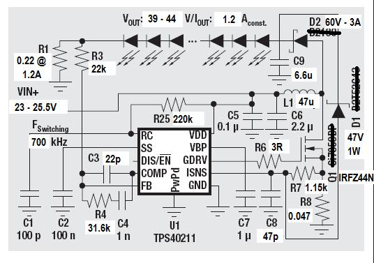
I have designed a boost led driver which drives 12 power LEDs in series with 1.2A constant current. LED string and power supply voltages varies 39 to 44V and 23 - 26V respectively. I made the calculations for %20 p-p ripple with 700kHz switching frequency from the information given in product datasheet. I attached the schematic to post.

When i powered the system LEDs started flashing. I first thought soft start cap should be bigger value than i put a 1uF but this only changed flashing speed. This meant that driver was sensing an overcurrent state so i lowered Isense resistor but didn't work. Than i tried to decrease LED current and flashing stopped at 350mA. Since than i tried a few things too but couldn't stop the flashing above 350mA current.

I hope i could have explained the situation well. Waiting for possible reasons and solutions for the problem. Thanks in advance.


  • I suspect that your issue is the over-voltage protection circuit pulling up on the current limit pin.  D1 is a zener diode that pulls up on the ISNS pin if the output voltage exceeds the expected maximum voltage, but it is feeding a 1.15kOhm resistor with a 100mV threshold, so the converter will trigger OCP and restart if the zener diode conducts 100uA of current.  Your 47V 1W zener diode might be conducting 100uA of current a little below 47V and tripping this OVP circuit a little early.

    You could try 2 different ideas on this:

    Decrease the ISNS impedance by reducing R7 and increasing C8 by the same factor (try 2x) which will require 200uA of zener current.

    Try a 51V or lower current 47V zener diode.  This zener diode is never going to see a lot of power dissipation.  As soon as it conducts 100uA of current, the converter will shut-down and restart.  At most, it's going to see 100uA continuous current if it's on the very edge of triggering OCP.  That's a worst case power dissipation of 5mW.  It doesn't need to be a 1W zener.  A 100mW zener diode will more than suffice, be smaller, less expensive and have lower zener current below its zener voltage.

    If you don't have a smaller zener diode or higher voltage diode, try adding 40kOhm series resistance.  This will increase the zener voltage 4V @ 100uA forward current, the equivelant of going from a 47V to 51V zener in this application.  In the end, I would recommend a 100mW 51V zener for that location in this application.

    If that doesn't work, here are some additional things you can try:

    1) As a check, try reducing the bandwidth of the control loop.  The control loop needs to adjust for changes in LED forward voltage, which is typically a slow process.  Try changing C3 to 220pF, C4 to 10nF and R4 to 3.16kOhms.  This will reduce the loop-gain by 20dB and provide a more stable control loop.  If the issue is stability resulting in higher peak inductor currents, this should address it.

    2) Right now you are using a 54ns time constant filter on the current sense.  This is following the datasheet recommendation, but it offers very little filtering of the gate-drive current pulse.  The first thing I would try would be to increase this.  Increase C8 from 47pF to 150pf.  This should filter much more of the initial gate drive pulse from the ISNS signal and provide a more accurate current limit function.

    3) R6 provides a series resistance to the gate drive, reducing the gate drive current and slowing the turn-on.  Increasing this to 10Ohms will increase switching losses slightly, but reduce the initial "spike" on the current sense by reducing the gate drive current.