


We have a situation where some of our prototype boards are failing to continue charging our batteries.
I've gone through all the requirements for charging to be enabled for the BQ24725A and all are valid conditions.
What I'm seeing is that the Charger IC isn't properly driving the hi and lo MOSFETs that control the charging voltage to the battery.
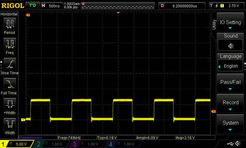
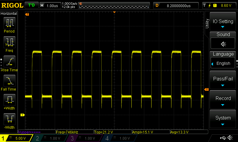
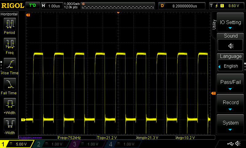
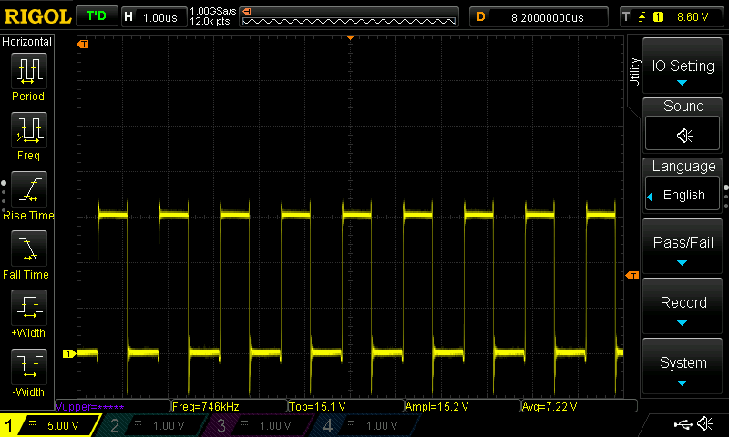
Under working conditions we see a nice square waves on these pins at roughly 735kHz (including btst and phase too).
Working LoDRV:
Working Bootstrap:
Working HiDRV:
Working Phase:
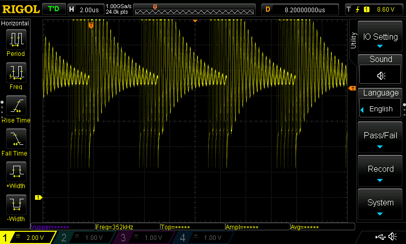
Now, when we compare the working to the non-working charger ICs, we see massive ringing and no square waves generated at all.
Failing Bootstrap:
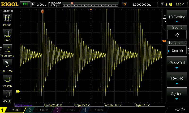
Failing HiDRV:
Failing Phase:
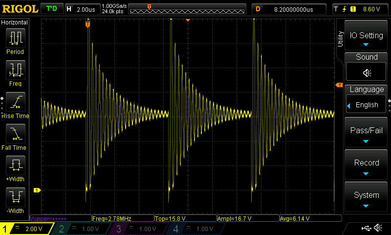
Does anyone have any insight into what might have caused our Charger ICs to start ringing instead of charging our batteries properly?
Thanks
-Mike


