Hi,
Please let me know whether there's any potential problem on below schematic.
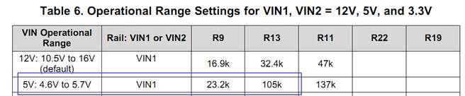
1. OVLO/OVP : 4.6V~5.7V
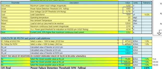
2. Current Limit : 2.1A
TPS25944A_SCH_REV01_20180221C.PDF
thanks,
TS
Hi,
Please let me know whether there's any potential problem on below schematic.
1. OVLO/OVP : 4.6V~5.7V
2. Current Limit : 2.1A
TPS25944A_SCH_REV01_20180221C.PDF
thanks,
TS