This thread has been locked.

If you have a related question, please click the "Ask a related question" button in the top right corner. The newly created question will be automatically linked to this question.

TPS65910: About power down on TPS65910Ax

Part Number: TPS65910

Hello,


Regarding to switch-off sequence time at power down on TPS65910Ax(EEPROM Configuration mode) ,

my customer is asking a question.

(Question)

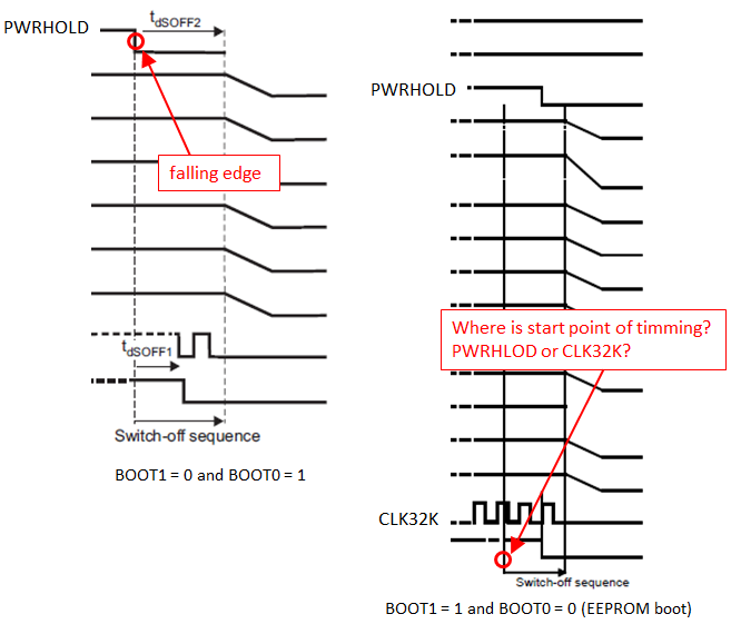
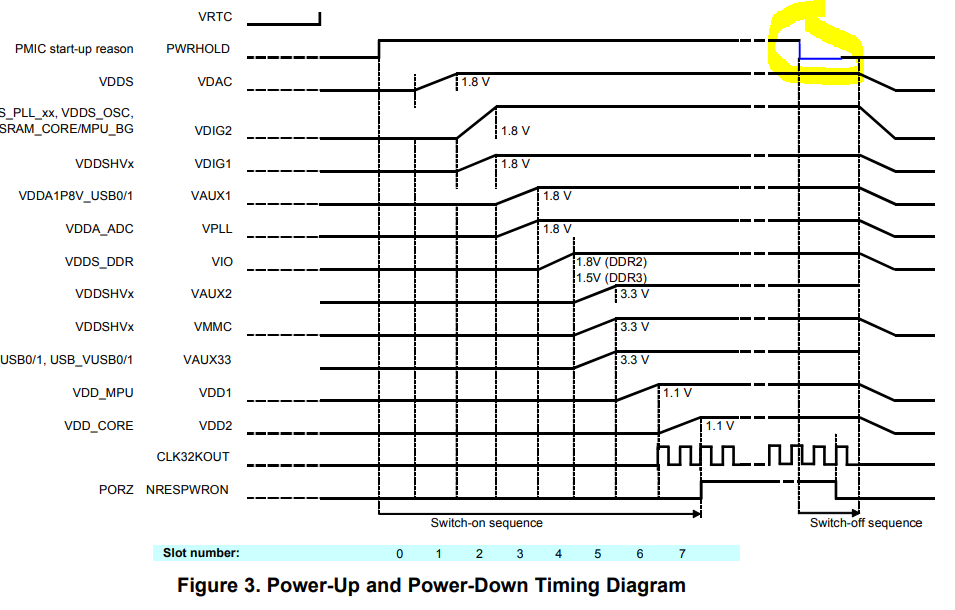
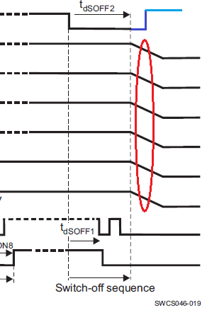
(1)The contents of switch-off sequence time (tds OFF2) is deferent between datasheet Figure 5-2(page 39) and User's Guide Figure 3 (page6).

They think that datasheet Figure 5-2 will be correct. Their understanding is correct?

(2)After tds OFF2, when power-up is executed again by PWRHOLD(L->H) at remaining some output voltage, is there any impact to TPS65910 or AM335x?

(When power-up is executed again remaining some output voltage, is there any problem?)

The each output capacitor value are same as schematics of AM335X_ICE Board.


Regards,

Tao2199

  • The TPS65910 datasheet shows the power-up sequence Fixed Boot Mode: 01b in Figure 5-2 where BOOT1 = 0b and BOOT0 = 1b, and the associated Table 5-3 shows the time slots for each power rail. For example, VDD2 time slot is 4 in this table.

    The timing diagram shown in Figure 3 of the TPS65910Ax User's Guide for AM335x Processors (SWCU093F) shows the power-on sequence for Boot Mode 10b, where BOOT1 = 1b and BOOT0 = 0b, and the associated Table 2 shows the time slots for each power rail. For example, VDD2 time slot is 7 in this table.

    Both of the above mentioned tables match the timing diagrams in the figures, so it is my understanding that both diagrams are accurate. The diagrams are simply showing different power-up sequences based on the hardware pin-strapping of BOOT1 and BOOT0 pins.

  • Hello Brian,

    Thank you for reply.


    I understood about difference power sequence at boot mode.

    I have additional question about timing of switch-off sequence time (tds OFF2).

    a) In case of BOOT1 = 0 and BOOT0 = 1

    According to datasheet Figure 5-2(page 39), it is started from falling edge of PWRHOLD.

    b) In case of BOOT1 = 1 and BOOT0 = 0 (EEPROM boot)

    We referred User's Guide Figure 3 (page6) but we couldn’t make clear about starting point of tds OFF2.

    Could you please tell us about the starting point of tds OFF2 at this mode?


    Regards,

    Tao2199

  • Tao,

    The Power-Down timing diagram in Figure 5-2 in the datasheet is correct, showing tdsOFF2 and tdSOFF1 clearly.

    The Power-Down timing diagram in Figure 3 of SWCUF093F User's Guide is incorrect: PWRHOLD should go low when the left vertical dotted line reaches the PWRHOLD portion of the diagram.

    Please refer to my hand-drawn edit of this drawing: