


My current design needed 1.0V @ 6.0A in addition to 2.5V@1.0A for operation. Since TI had a verified reference design for a load shared arrangement on a similar part I selected the TPS7A85 which also could be load shared. Now that I am integrating the design, I can't seem to get the TPS7A85 to operate in the adjustable feedback mode. Both the load shared LDOs (for 1.0 V) and the single LDO (for 2.5V) seem to oscillate at just above 1.0V. For ease, I will refer to the 2.5V carrangement since it is NOT load shared.
The parts appear to be properly oriented. Input voltage is 3.3V. The PG signal is low. I actually used the TPS7A85A datasheet but for some reason the 'A' got dropped off the BOM and ended up with the TPS7A85 part which I will swap out once I get the design functioning. Circuit is straight out of the data sheet from Figure 50 (Figure 49 for the TPS7A85) and is attached.
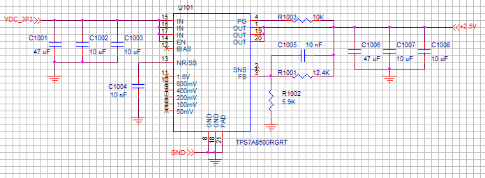
The Feed forward cap is utilized in the 2.5V LDO but not populated in the 1.0V load shared arrangement. Note that the only real difference in there is no cap on the BIAS pin since the datasheet states "The use of a BIAS voltage improves dc and ac performance for VIN ≤ 2.2 V." and "If not used, this pin must be left floating or tied to ground." There are no negative voltages on the board. There is no reverse current protection diode currently (paragraph 8.1.7).
What am I doing wrong here? I could see if the 1.0V load shared arrangement didn't work but the stand alone 2.5V regulator behaves the same way. Anyone have suggestions?
