This thread has been locked.

If you have a related question, please click the "Ask a related question" button in the top right corner. The newly created question will be automatically linked to this question.

Voltage drop using TPS61222....

Other Parts Discussed in Thread: TPS61222

Hello! 

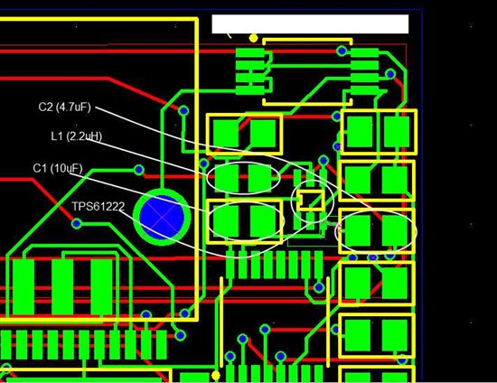
I am  using a TPS61222 low voltage step-up converter in a design.  It has a fixed output voltage of 5V.  Cin = 10uF, Cout = 4.7uF, L = 2.2uH (inductor rated for 900mA).

The circuit I am feeding must be 5V.  The supply voltage to the booster circuit will be 2.7V, 3.3V or 5V.  When there is little draw on the circuit (<2.5mA), the voltage is right where it should be at 5V, but when there is a draw of more than 2-3 mA, the output voltage of the boosting circuit drops quickly.  I have no experience with this device.  Any ideas of where to start looking?

Thanks for your help!!!

Beau

  • Make sure that your PCB layout follows the recommendations in the datasheet.  You can also order the EVM to do your testing on it, knowing that it has a good layout.  Can you post your layout?

    Also, what are you using for your input supply?  What voltage is it?  Have you verified that it is not current limiting?

    Have you measured the output current to make sure that it is what you think it is?

    Can you post a scope capture of what the Vin, Vout, and L voltages are doing when the circuit is working and then when it isn't?

    These are just some things to begin looking at.  This is a simple part, so I sure you will be able to find what is wrong.

  • Well, I'm still having issues.  Here is the layout:

    I have used two different voltages for the input power supply: 5V, 3.3V.  I have verified that current limiting is not an issue.  When the TPS61222 outputs more than a few mA, the voltage drops to the input voltage, then declines as Iout increases.  After initial problems, I put only the boosting circuit on a board for testing, and used a varister connected to Vout to troubleshoot the failing point of the circuit.  Here's the inductor that I am using: http://www.mouser.com/Search/ProductDetail.aspx?R=GLFR2012T2R2M-LRvirtualkey52130000virtualkey810-GLFR2012T2R2M-LR  Is this inductor an acceptable choice for this circuit?

    Thanks for your help

  • Your inductor looks ok for light loads, but note that it saturates at 400 mA.  The IC regulates an inductor ripple of about 200 mA peak to peak.  The peak inductor current should not be greater than its saturation current.

    The traces on your layout look very thin.  How wide are they?  We need to look at Vin, Vout, L, and the inductor current with a scope to understand what is going on.

    You can order the EVM and that way debug a board with a known good layout.