This thread has been locked.

If you have a related question, please click the "Ask a related question" button in the top right corner. The newly created question will be automatically linked to this question.

LM5020: Over current protection is not working.

Part Number: LM5020

hi

 I will deliver the corresponding circuit diagram and transformer specification. Is it possible to review the circuit?

Over current protection is not working.

I think there is a problem with the trance design. Should I reduce the size of my trance?

What additional precautions do you have?

EAX67343206-2.2-SCHE_PDF.pdf

Trams 17POC-LS01 EFD3130 2018.01.03.pdf

  • could you please clarify what do you mean exactly by OCP not working?
  • hi

    The present input voltage is 28V Output DC (12V / 2.2A) specification.

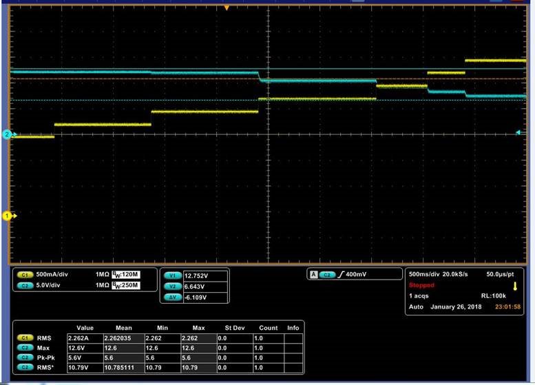
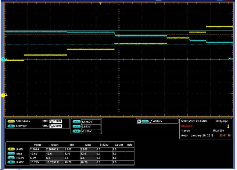
    When the secondary side is short, the current rises to 9A and the voltage drops slowly.(CH1 = Iout, CH2 = Vout)

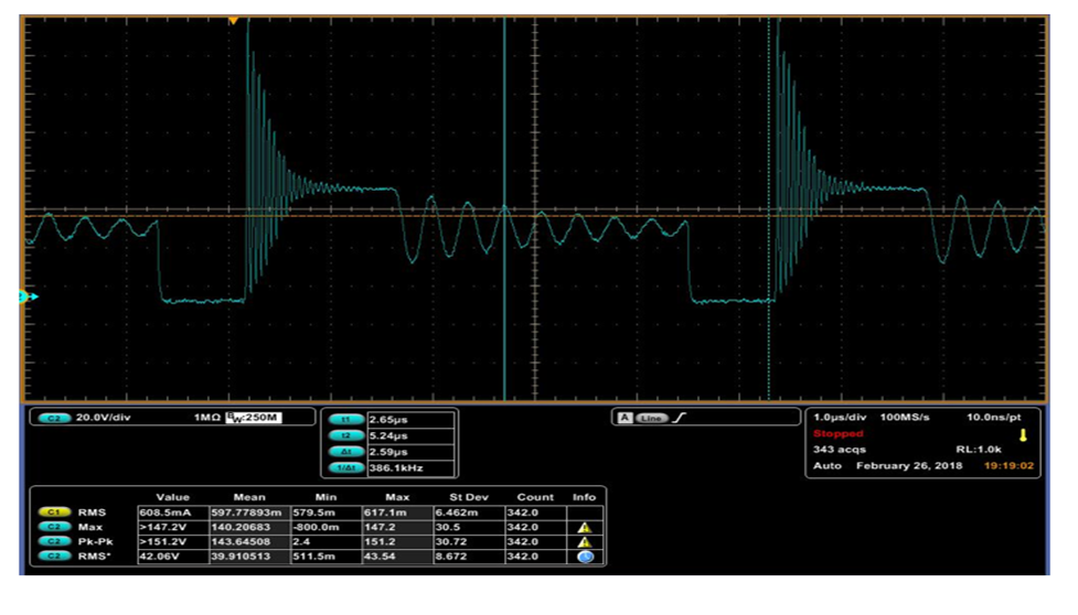
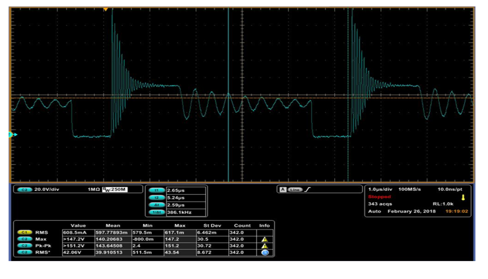
    VDS ringing occurs during normal operation

  • hi

    The present input voltage is 28V Output DC (12V / 2.2A) specification.

    When the secondary side is short, the current rises to 9A and the voltage drops slowly.(CH1 = Iout, CH2 = Vout)

    VDS ringing occurs during normal operation

  • the 2nd waveform shows deep discontinuous conduction mode, implying a high peak current. Please replace the power transformer with one having higher primary inductance (47uH or higher), which will help the converter in continuous conduction mode and lower short circuit current.
  • It is said that the mass production schedule is near and the trance can not be changed. So I changed the mode to CCM mode and did not proceed to TEST. I had to remove the CAP (100pF) of CS-GND while I was reviewing it by other methods.
    The OCP operation was similar, but the level of heat generation of the FET was reduced so that it was not damaged.
    Would not it be a problem to do so? Is there anything else I need to review?
  • We usually do not recommend to completely delete the CS capacitor. It helps filtering out the current sense leading edge spike and prevent its effects on the normal PWM operation. You may reduce it but do not delete completely.

    By a simple calculation, it seems your current sense resistor of 20mOHm is too small. You should double that value and reduce the overloading headroom. This my reduce y our short circuit current a lot.

    The severe ringing on your Vds means an ineffective snubber. It could be resulted from PCB parasitic inductance in the path of the snubber. It becomes worse if you have a large di/dt, which seems to be the case for your 5uH transformer: a large peak current.

    If no PCB can be changed, try to increase the current sense resistor value.