This thread has been locked.

If you have a related question, please click the "Ask a related question" button in the top right corner. The newly created question will be automatically linked to this question.

LM25011: Failure of the LM25011 - SW-Pin in short circuit with GND

Part Number: LM25011

Hello,

I have an application where I use the LM25011 to charge a 3F capacitor and to hold the voltage at about 19V when the charge is finished.

Vin = 24V (+/- 10 %)

During the charge, the regulator works in current limit (ajusted at 1A).

The Problem we have is that sometimes a failure of the LM25011 occurs. The charging of the capacitor doesn't works and you can see a burn mark on the package of the LM25011 (see Picture attached).

Up to now, this failure occured only sometimes during the final test of our production line.

At the Moment, I couldn't reproduce this failure by doing tests in the laboratory. I could just mesure a short circuit between the SW-pin and GND. So I presume that the pre-charge circuit ist defect.

Do anyone of you have an Idee why this failure occurs and why only sometimes?

I have also attached our schematic.


Thank you in advance for your help!

Simon

  • Hello Simon,

    Looks like Pin 1 side of the IC is destroyed, even though you have a short between Vsw and Gnd? Can you confirm? Also can you post the schematic as I did not see the attachment?

    Thanks.

    David.
  • 1641.Schematic.pdfHello David,

    Yes. I confirm that we have a short between Vsw and GND and that is the case with all defected LM25011. 

    I also measured the resistance between Vin and Vsw. In some cases, you measure about 300 Ohms, in other cases a little bit more (for example 2k2, but it isn't a whole stable value). I did the measurements without other parts around the LM25011.

    Can you see the schematic?

    Simon

  • Thanks for the Schematic and confirmation Simon.

    When failure occurs does it occur during start up?  of does it occur as soon as you apply the input voltage?  Or does it occur in another state? 

    Can you confirm that the output is well clamped at 20V.  

    Do you have the part number for the inductor you are using?

    Can you take a scope capture of switch voltage and inductor current during normal operation while Cout is charging?

    Thanks.

    David.

  • Hello David,

    I don't know when the failure exactly occurs because it occurs during our final test in production (but not often). So I couldn't measure it up to now. We just get the failure Information of our device, where the LM25011 is build in, that the charging of the ultracapacitor didn't works. So, it can occur during start up. Can it be a problem of the soft-start capacitor (I have a 15nF)?

    The output is ajusted to 19,4V and that works well.

    We use following inductor: 7447714100 from Würth Elektronik.

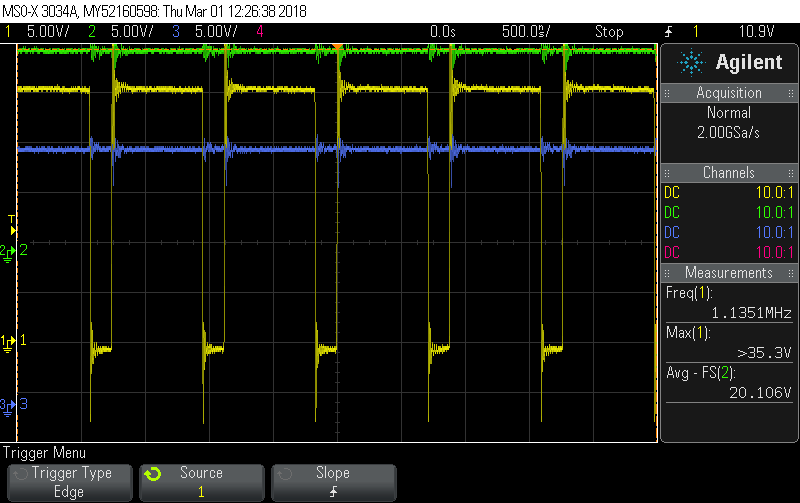
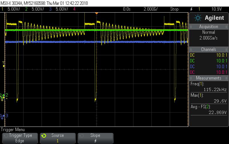
    I don't have the scope capture of the inductor current at the Moment. But I can already show you the waveforms of the switch voltage when the regulator works in continuous (during charging) and discontinuous current mode (wenn the 19,6V at output are reached) (see attached files).

  • The scope capture waveform's look very stable.

    The inductor is ISAT is specified to be more than adequate.

    Not sure if the SS cap will help as you are very likely going to operate in current limit (which is normal)? Please can you confirm, the the time it takes to charge 3F is much greater that the SS time determined by Css?
    The LM25011 has an ideal current limit function for your application (Super cap charging) because it implements a valley current limit, followed by a peak current limit. The Peak current limit is implemented by reducing the TON time by 40%, after valley current limit has been violated. You should be starting up and charging the Super Cap, as the voltage is increasing, it should be doing so in current limit, Set by the Rsense and Ton (And inductor value)? You can try and increase Css if failure occurs instantly when you apply input voltage?

    Do you have an input filter at Vin? Usually, its an over voltage condition that causes catastrophic failure. If you have an input filter that is undamped, this could cause excessive ringing at Vin, which could exceed the abs max Vin rating of the LM25011? We should rule this out?

    Hope this helps?

    David.
  • Hello David,

    Yes. The charging of the 3F output capacitance takes about 60 sec. The SS time according Css=15nF is about 4 ms.

    We plan to do some tests on the production line and measure the electrical signals.

    So I hope I will get more details about the failure.

    Thanks.

    Simon