This thread has been locked.

If you have a related question, please click the "Ask a related question" button in the top right corner. The newly created question will be automatically linked to this question.

TPS40210 Design Problem for LED Backlight Power Supply

Other Parts Discussed in Thread: TPS40210, TPS40211

Hi Gents,

I am designing an boost supply of LED backlight for TV LCD panels. The design parameters are:

Vin: 19V - 24V

Vout: 43V

Iout (max): 2A


And when I input these parameters to SwitcherPro Desktop Version, it show that it cannot complete the design using these parameters.

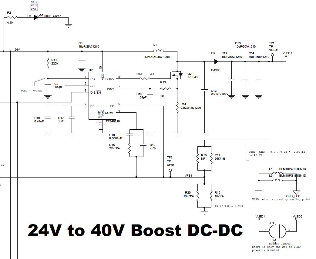
Based on hand-calculation, I made this circuit:


Fosc is set to about 700KHz

Duty cycle is about 44% for 24V input

A 12uH inductor is chosen to avoid saturation


I got the following problems:

1. This circuit cannot output 2A if the Rsns is 22mohm. It limits the inductor current and the output voltage drops when the load exceeds 1.4A. Should I decrease the Rsns?

2. There is a lot of ripple at output. For 1A load, the ripple is about 5V (output voltage is 43V). And the ripple frequency is about 16KHz, resulting to a humming sound on the inductor.

Could anybody tell me the relationship between the frequency of output ripple the the value of the other components? How should I make the ripple frequency higher than 20KHz so that it is not hearable ? To modify the compensation loop?


BTW, it is noted that TPS40210 is removed from the online version of SwitcherPro, "due to design problem". Does anybody know about this?


Thanks!


Bird

  • Bird,


    First, I would recommend considering the TPS40211 controller in an LED drive configuration (controller regulates the voltage drop across a series ground resistor rather than the voltage at the top of the LED string) for an LED application.

    1. This circuit cannot output 2A if the Rsns is 22mohm. It limits the inductor current and the output voltage drops when the load exceeds 1.4A. Should I decrease the Rsns?

    A rough calculation of the switch current at 1.4A at 40V out and 24V input comes to 2.33A.

    24V input @ 44% duty cycle with a 12uH inductor is showing a peak current of 3A for a sensed peak of 66mV, which should be working, however the 16kHz oscillation is likely resutling in more current draw during the rising edge and that is likely the cause of the current limit at 1.4A.

    2. There is a lot of ripple at output. For 1A load, the ripple is about 5V (output voltage is 43V). And the ripple frequency is about 16KHz, resulting to a humming sound on the inductor.

    This is likely a loop stability issue.  Without looking at the loop in detail, let's just back the loop bandwidth off.  Between FB and COMP pins there should be 2 capacitors and 1 resistor.  (R15, C18 & C19)  Looking at the values, the bandwidth is quite high.  Try changing C18 from 6.8nF to 68nF, R15 from 27kOhm to 2.7kOhm and C19 from 2.7pF to 270pF.  That will back the loop gain off and also pull the high-frequency pole down from 2MHz down to 200kHz.

    BTW, it is noted that TPS40210 is removed from the online version of SwitcherPro, "due to design problem". Does anybody know about this?

    Yes, we are aware.  There were some issue with the calculations being used within Switcher Pro that were resulting in improper component selection.  We are working to correct the calculations and return the TPS40210 controller to the SwitcherPro software.