This thread has been locked.

If you have a related question, please click the "Ask a related question" button in the top right corner. The newly created question will be automatically linked to this question.

TPS92513HV: MOS trasnsistor shortcut over 36V

Part Number: TPS92513HV

Hi,

We have a LED drivers design where 3 LEDs are powered at 450mA and we are breaking all the prototypes we are testing.

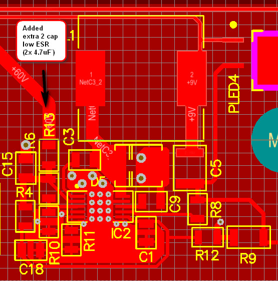
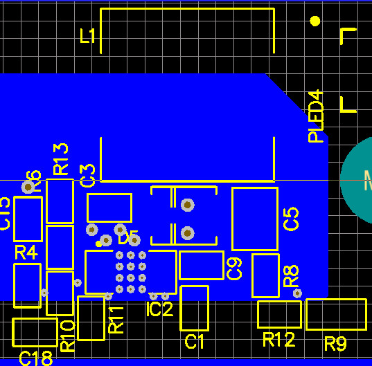
This is the original design where some values have been changed:

The C15 value is now of 10uF and R9 is 0.68ohm (to adjust to 450mA).

We have also modified R10 to 18K to start lighting at lower input but with the same result.

We have an external power supply (0-60V) and we increase slowly the VIN from 0.

At about 13V the LEDs start lighting and become stable up to 30V. At about 36V input the TPS breaks.

It is HV so it should support a maximun of 65V but we have tried in about 5 prototypes and all of the does not support more than 36V input.

The result is always the same, the MOS transistor broken (ussually shorcut VIN and PH).

We have replaced the TPS with another new, and again they brake.

The most amazing thing is that in some previous prototypes with the same circuit they are running perfect at 55V input.

They are in burning for 24h and they are running (one died this morning without any action).

Sincerely, the TPS seems to be very weak or we are not taking in count something that breaks the transistor.

Coudl you help us?

Many thanks

  • Hello Ruben,

    Did anything change between the previous prototypes and the current boards? Is there any way you could share the layout of your circuit and possibly the BOM? The schematic looks ok, but noise generated by layout (and/or not soldering the DAP down properly) is the most common cause of damage at higher voltages. If there is a lot of noise you can exceed abs max conditions or certain nodes (like PH) could even be pulled too far below ground causing substrate injection.

    I would be happy to look over your layout for issues if you can provide it. Thanks.

    Regards,

    Clint

  • Hi Clint,

    We used the same layout (same PCB) for previous and new prototypes.

    There is only one difference between them and this is the way of manufacturing them.

    First ones where mounted in R&D by hand, placing paste by hand and soldering them in the oven.

    Second prototypes were mounted using stencil and P&P machine but nothing else.

    It is true that we are having some of them able to run at 50V from second prototype batch but we have such a mess about what we have (too many tests and getting lost with so many changes and tests).

    I attach you the layout of both layers, top and bottom. 

    As mentioned, we added manually low ESR two 4.7uF capacitors in the input before BLM ferrite.

    Regards,

    Ruben

  • Hello Ruben,

    The layout doesn't look bad, and increasing input capacitance is critical for a buck converter. But 10uF should be ok. I'm more concerned about assembly. I can't be sure but I know these parts are pretty robust. I have seen in the past where our techs solder the DAP well and there are no issues. Then when we have done assembly out of house the DAP would not be soldered correctly, especially when using lead free solder. That could cause issues and damage, is there any way you can verify the DAP connection? Usually that means an x-ray, but it has been an issue. If things were fine before but not now it's worth looking into the difference. If you can verify the DAP integrity and still have problems we can dig deeper.

    Regards,

    Clint

  • Hi Clint,

    After your response about DPAD, we checked with XRAY if they were correctly soldered and more or less they were.

    The worst cases we have seen they were with about 80% of the surface soldered, but mainly they were correct.

    Taking your ideas in count and looking only at VIN pin, after having added a new 4.7uF/100V capacitor in the VIN pin (we have 3 capacitors now), all the prototypes are stable and running.

    Thanks for your advices and we will come back again if we have any other questions.

    Many thanks,

    Ruben