This thread has been locked.

If you have a related question, please click the "Ask a related question" button in the top right corner. The newly created question will be automatically linked to this question.

BQ76PL455EVM: No UART response

Part Number: BQ76PL455EVM
Other Parts Discussed in Thread: TMS570LS1224, BQ76PL455A-Q1, HALCOGEN

Bought the bq76pl455-EVM and TMS570LS1224 development boards to develop code for an electric car battery management system. I've checked the bq76pl455-evm board with the provided TTL-USB adapter and the provided TI PC software to make sure it works (which it does).

I have used a 5v - 3v3 level converter between the SCI_1 (non-LIN) (Product: www.amazon.co.uk/.../ref=od_aui_detailpages00 ) and the bq76pl455-EVM board, as the TMS is 3v3 and the bq76pl455-EVM is 5v.

Using the bq76PL455A-Q1 example code provided by TI (intended for the TMS570LS04 development board) as a base I've changed the UART interface from the SCILIN to SCI (as this is what we will be using in the PCBs that we will be making based on the two development boards), made sure the interrupts work on the new SCI interfaces.
In HalCoGen, I've made sure the pull-ups are enabled on the SCI interface, and the GIOs directions are set correctly (Using GIOA_0 for wakeup and GIOA_1 for fault). The baudrate is set to 250k in HalCoGen.

Currently, when using the TMS570 to try and send commands to the bq76pl455-EVM (which should get a reply response) I get nothing from the bq76pl455-EVM. The RX line is silent, and stays high as probed from an oscilloscope.

The LED on the bq76pl455-EVM lights up when the TMS570 board is powered (I've also used a separate power supply which can supply more power just in case the power rails were dropping, which they weren't).
I've probed the bq76pl455-EVM board for if the signals can across to breadboarded TTL level converter, the TX and WAKEUP can successfully get to the EVM board.

I've tried running the full example code (adjusted pin-out for my use case) so that it should fully wake the EVM up and configure it and then ask it to do a ADC read command, as well as just sending a single while looped (with delay) ADC sample command.

Also tried using a mbed LPC1768 which we had lying around to try and send ADC read commands to the EVM over the UART interface with to no avail. And have verified using a TTL adapter for a PC that the TMS570 is sending at 250kbaud to a computer, and the interrupts so that I can send to it.

I'm at a loss as to why the bq76pl455-EVM is not responding to anything apart from the PC. Nothing that has been received after any commands sent from the TMS570LS1224 development board or the briefly tested LPC1768.
Does anyone have any hints as to why this is not working, or anything that I seem to have missed?

I've attached the code that I'm using, but does not seem to work.

TMS570LS1224_Code.zip

  • Hi E.,

    Could you share a picture of your setup?

    If possible, I would also put a logic analyzer on the pl455 RX pin to make sure it is receiving the data that you think it is. That will be the biggest help.

    I'll take a look at your code and see if I find anything.
  • Hi David, 
    Thanks for your quick response,
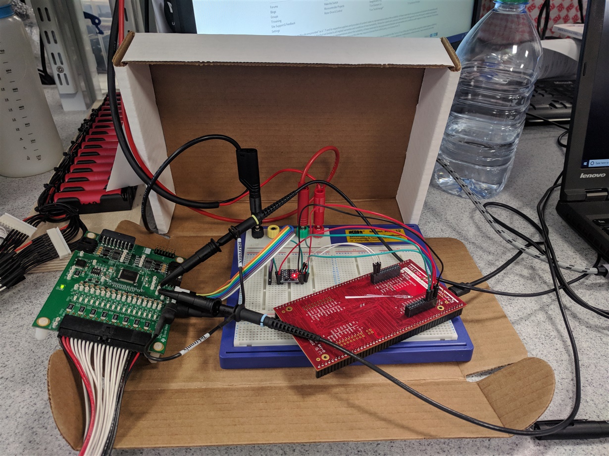
    Here's a picture of my setup:
    The power in the picture is coming directly from the TMS board, not from the banana connectors.
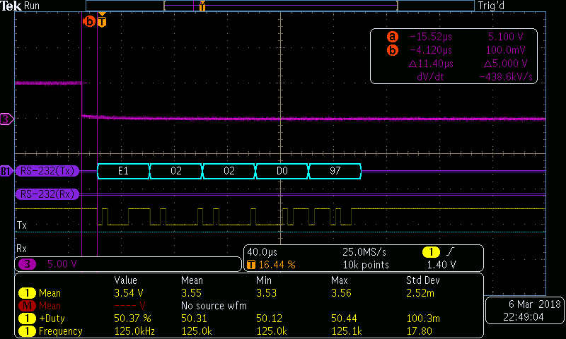
    I put a logic analyser on the TX and RX pins (As labeled on the silk screen), and a probe on the Wakeup line as well (purple).
    I intended to send the hex codes: {0xe1, 0x02, 0x02, 0xd0, 0x97}
    This correlates with what the scope reads (MDO3024 scope).
    The scope is setup with 250kbps, 8 data bits, no parity, for UART mode it required inverted polarity (HIGH = 1).
    Using this while loop to send the data:
    uint8 send[5] = {0xe1, 0x02, 0x02, 0xd0, 0x97};
    while(1){
    WakePL455();
    // sciSend(sciREG, 5, send);
    sciSendByte(sciREG, 0xe1);
    sciSendByte(sciREG, 0x02);
    sciSendByte(sciREG, 0x02);
    sciSendByte(sciREG, 0xd0);
    sciSendByte(sciREG, 0x97);
    delayms(100);
    }
    Did originally use the commented out line, but it made no difference when sending them Byte-by-byte.
    The wakeup line sends a 24ms pulse (using the supplied function), which gives an actual 19ms pulse.
    When trying to trigger of the RX line (as per silkscreen) the scope doesn't trigger, implying that nothing is transmitted back to the TMS board.
    Thanks for your help so far, did you manage to find anything with the code? Going to continue to debug my end.
    Kind regards,
    Ed
  • Hi Dave, 

    Thanks for having a look through everything.

    I decided to check the the schematics to see if I had wired the communications interface correctly - After I made sure that was the correct way around I re-ran the code. So the reason why the code wasn't doing what I thought is I only have 1 slave board attached but the example code seems to be written for 3 boards.

    So it was forever getting stuck waiting for a response. Using the logic analyser I found that it had been responding to some commands, just not the ones I was checking with break points because it was trying to index boards that didn't exist.

    Thanks for your help and pointing to use the logic analyser.

    Kind regards,

    Ed F

  • Hi Ed,

    Glad you have made a breakthrough! A logic analyzer is one of the best tools to have in your  belt for debugging these things, in my opinion. I swear by mine.