This thread has been locked.

If you have a related question, please click the "Ask a related question" button in the top right corner. The newly created question will be automatically linked to this question.

BQ24040 ~CHG

Hi,

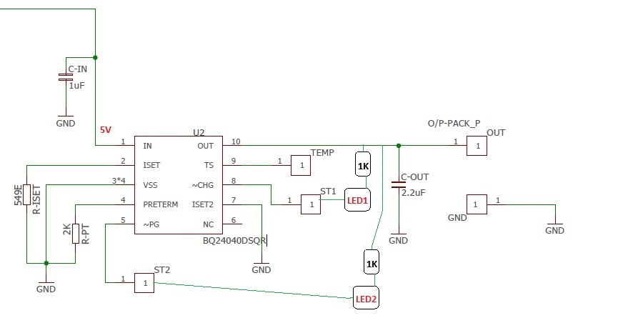
I have implemented circuit for battery charging as seen above.

Input voltage = 5V

Output Voltage measured = 4.2V which is connected to Single cell Li-ion 3.7V 2600mAh battery.

Case1:

Both LED's were ON during charging and LED1 went OFF at 3.65V after 2 hours.

Case2:

Voltage on ST2 (~PG) = 0.07V where LED2= ON

Voltage on ST1 (~CHG) = 2.5V where LED1 = OFF

During the second trial LED1 is showing OFF (but battery is charging).

Why I am not able to see LED1 indication as ON while charging during my second experiment?

Also at what voltage LED1 should turn OFF in CASE1 indicating it has entered termination charge state?

Thanks in advance.

Regards.

Rahul

  • During Case 1 and Case 2 what is the input current?
    Try testing with 10k pull down resistor on TS pin.
  • Input current is 1A.
    Output current does not go to fast charging (which is set to 0.983A) but starts at 0.381A (with battery voltage as 3.03V) and then gradually decreases to termination current as per datasheet to 0.098A with battery voltage 3.65V.

    What should be the full charge voltage on battery?
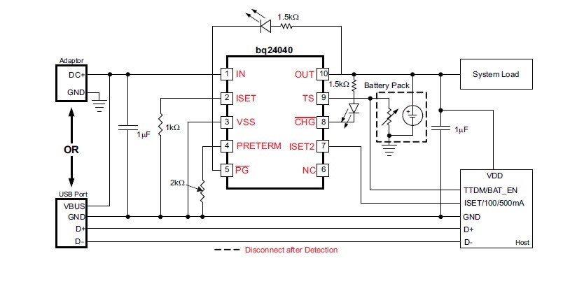
  • Currently TS pin is connected to Battery NTC of 10K as shown in datasheet.

  • Somethings to check:
    1.) Input voltage drop, Vin vs Vout -- If input voltage drops output current is reduced. Check for low input voltage under load.
    2.) Thermal Rise of device---Device has a thermal regulation feature, as temp increases the output current is reduced.
    3.) Check voltage at output voltage and verify that it is a DC level---Check if the unit may be entering battery detect, square wave at 25mS high low.