This thread has been locked.

If you have a related question, please click the "Ask a related question" button in the top right corner. The newly created question will be automatically linked to this question.

BQ24190: Input oscillation.

Part Number: BQ24190

Hi,

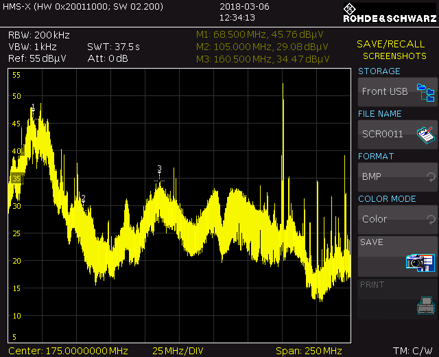
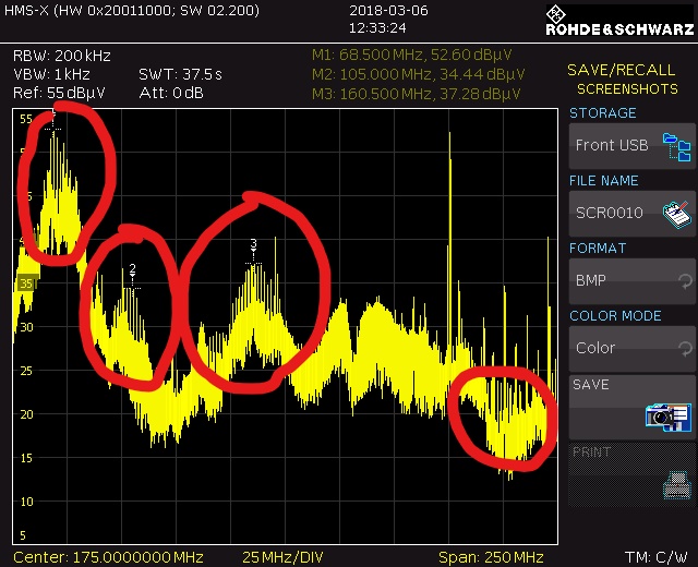
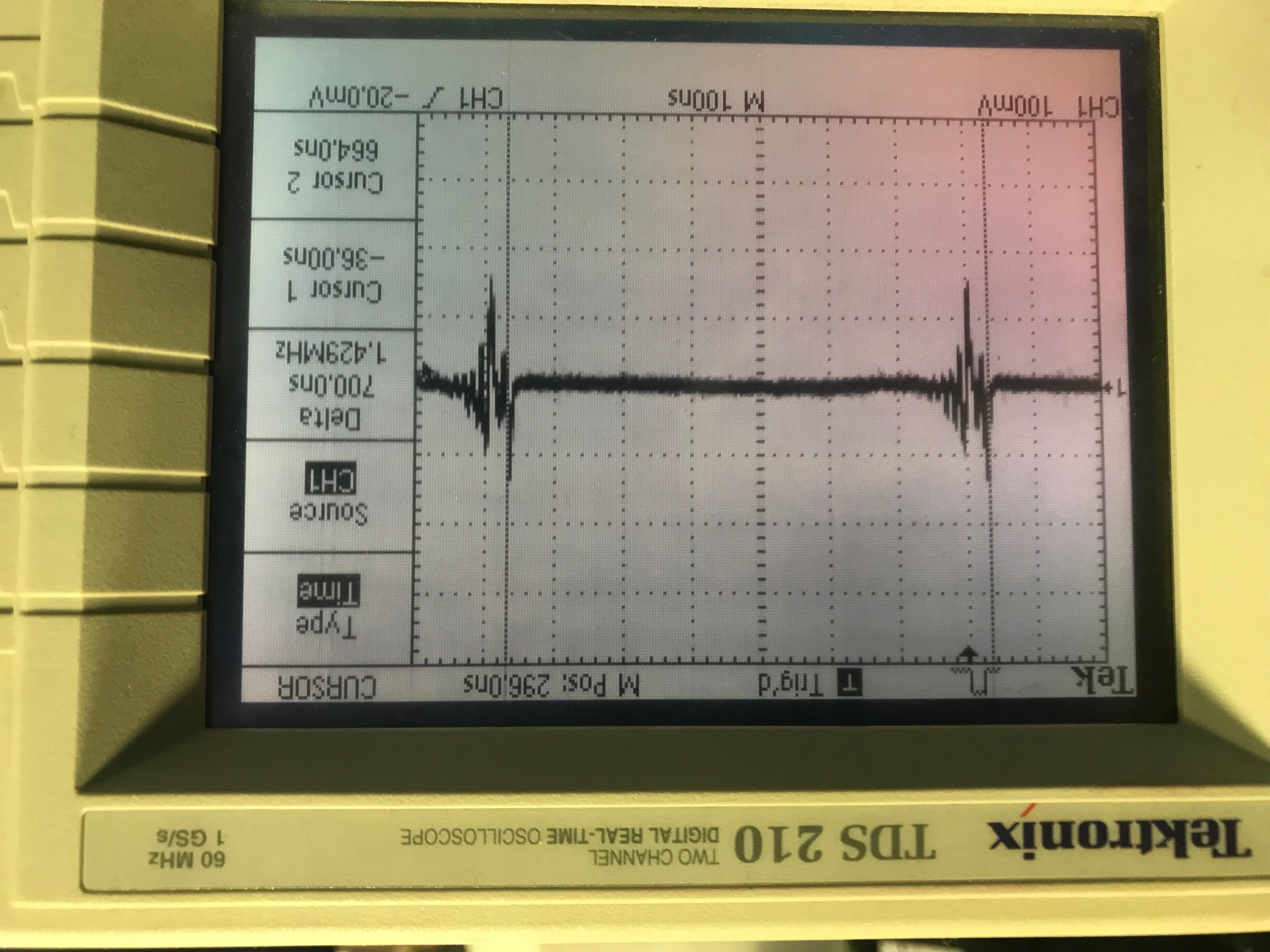
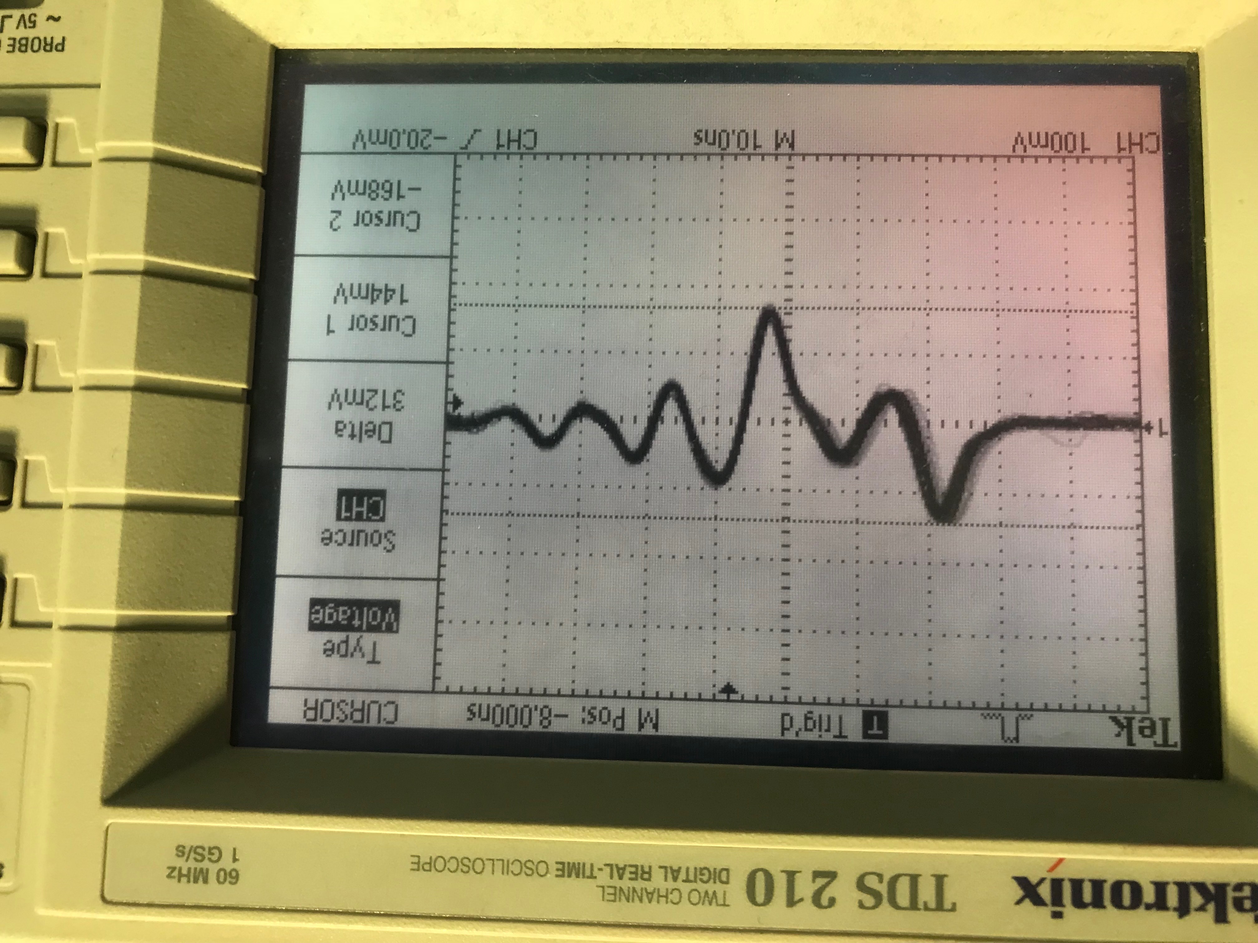
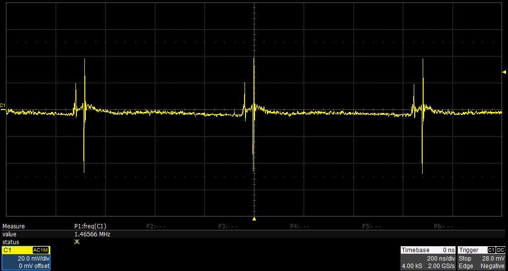
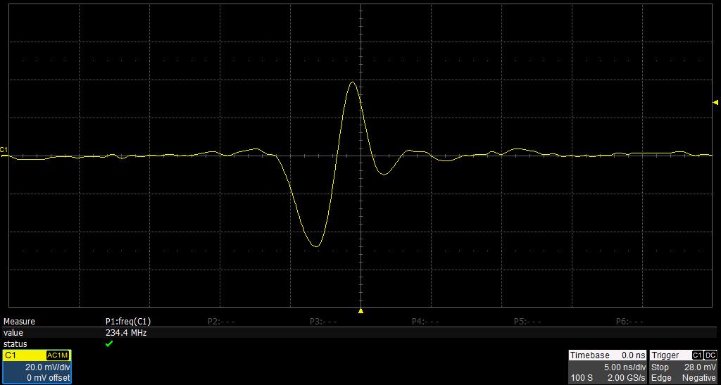
My input (VBUS) appears to be oscillating between ~200 - 300 MHz depending on the load & supply. 

I have tried adding a ferrite bead at the input, changing and adding input capacitance.

All appear to just shift the frequency around a bit, nothing reduces it.

Kind Regards,

Mark Burton

  • Hi Mark,

    What are your load and supply conditions when you are seeing this oscillations? Could you include any oscilloscope plots if you took any?

    It is possible that you are in a INDPM or VINDPM. What levels do you have set for these?

    Thanks,
    John
  • Hi John,

    All registers are default.

    My worst case is when connected to a USB on a laptop. I think the IINDPM could be the issue...

    Could you confirm I am correct with my thinking in these two statements:

    1) When I plug into a USB2.0 port, input current limit will drop to 900mA. However, Charge current will remain at 2048mA. Therefore the device would enter IINDPM.

    2) When I plug into my charging port (5v 2.2A usb plug) input current limit will be set to 1500mA. Charge current will remain at 2048mA. Again entering IINDPM.

    If the above is true, and this is causing the spurs I see, then I guess I should check what IILIM register is set to when it is plugged in and adjust the charge current ICHG register to keep it below IILIM?

    Thanks for the help.

    Kind Regards,
    Mark.

  • Hi Mark,

    The charge current setting is the max current that will be sent to the battery, if no other limit is reached. In both of those cases the actual charge current will not reach this level because of ILIM.

    I recreated the test conditions you described using the BQ24190 EVM and I was unable to see an input oscillation. Could you give me more information about how VBUS is delivered to in your system? Also, how are you measuring the various voltage and currents?

    Thanks,
    John
  • Hi John,

    VBUS can come from any USB port. and is directly connected via a 1uF capacitor. I have also tried putting ferrite beads in this line along with lower and higher value capacitors.

    The SYS output goes via an on/off button controller (LTC2950-2), controlling a MOSFET. The SYS output can supply the main product (if turned on) and would draw a maximum of 700mA when powered up. NOTE: I am doing must of the testing at the moment with the device powered off so only current is drawn to charge the battery.

    This is a reference  sweep with the device powered off and not charging.

    This is when charging from a laptop USB port and device powered off.

    BAT is connected to a 6.8Ah Li-Ion battery pack.

    I am measuring VBUS directly at the decoupling 1uF capacitor at the VBUS pin on the PCB.

    I am calculating input current by measuring VILIM and using the formula (Vilim/Rilim)*530

    Further testing info:

    Last night I fully charged a device, this morning when I plug it into the main power source (5V, 2.2A USB mains adaptor) I see no spurs on the spectrum analyser. When I plug it into the PC USB port, I can see them but they are very small. Indicating this worse when heavily current limiting on the front end.

    Regards,

    Mark.

  • Hi Mark,

    A 1uF cap on VBUS should be sufficient. how much capacitance is on the PMID pin? Higher frequency noise is filtered out on that pin as well. Our EVM uses a 6.8uF on PMID.

    Could you send me an oscilloscope waveform with VBUS vs. time? I want a better idea of the magnitude of this oscillation.

    Thanks,
    John
  • Hi John,

    Yes I have a 6.8uF only on PMID

    Below is VBUS with an oscilloscope. showing the 1.5MHz switching, I have then adjusted the time base to show the ringing. My oscilloscope is only 60MHz so not showing the higher order frequencies.

    Regards,

    Mark.

  • Hi Mark,

    Below is VBUS on the BQ24190EVM. This is with VBUS = 5V, VBAT = 3.9V, ICHG = 0.5A, no system load

    The frequency of this noise is expected, but it is clearly much larger for your design. Do you have a schematic that you could provide?

    Thanks,

    John

  • Hi John,

    Schematic for charge controller below:

  • Hi Mark,

    There does not seem to be anything in your schematic that would cause this. However, I have noticed that your schematic block does not have a pin 25 for the thermal pad. It is required for the thermal pad to be connected to ground for good performance. Below is the recommended layout for the BQ24190. 

    It is very important to have the PMID capacitor close to the IC in the layout. Also, note the thermal pad connected to the ground plane and use of vias. How does this compare with your design?

    Thanks,

    John

  • Hi John,

    Do you have access to a spectrum analyser to check out the higher frequencies? I am not convinced the differences we see on the oscilloscope are the cause.

    yes, I followed the recommended layout as a guide for my layout. See Below:

    one thing I have noticed on the recommended layout and the eval board datasheet is the provision for a resistor in the boost strap line. I wonder if adding some resistance would dampen it a little? what are your thoughts?

    When I probe the boost strap capacitor what I see on the spectrum analyser gets several times worse. Now this could simply be because the probe is acting as an antenna.

    Would it be possible to get me an evaluation board sent out?

    Regards,

    Mark.

  • Hi Mark,

    You can order a BQ24190 Evaluation Module from: www.ti.com/.../BQ2419XEVM

    I have two recommendations for ways to mitigate the high frequency noise that you are seeing:

    1. Add a 1nF Cap at PMID to GND. Use a X7R, 0402 and place it as close as possible to the PMID pin.

    2. Add a resistor in series with the boot strap capacitor. Adding this resistor will reduce the slew rate of your high side FET, which will mitigate higher frequencies that may be reflected back to VBUS. This resistor can range from 0 Ohm to 10 Ohm, but the exact performance is something that needs to be tested.

    Thanks,
    John