Hello TI Team,
We are facing another issue with BQ25120A:
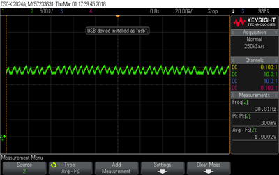
As we improved our product current consumption, it seems the we are sometimes running in PFM mode of the BQ25120A (see SYS screenshot below).
While SYS is set to 1.8V by default and not modified, we have 1.9V with 300mVpp (sometimes even 2V with 440mVpp depending on the board used) on the output with what looks to me as PFM mode.
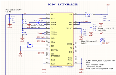
Looking at the datasheet, I can see that the recommended LC output filteris 2.2µH & 10µF, which is what we are using (see schematic below).
Our inductance is a Murata LQM18FN2R2M00D (0603 2.2µH 120mA 400mR, datasheet), which has a higher DCR than the recommended inductance listed in the datasheet, so I tried using a Würth 74479763222 (2.2µH 280mA 300mR, datasheet) to stay in the range of the recommended parts, unfortunately that did not help. I also tried to increase the output capacitance to 20µF, which helped reduce the ripple to 260-280mVpp. I tried 30µF but it didn't help any further.
Is there a way to force the BQ to use PWM mode?
If not, do you have any suggestion to help reduce this ripple and stabilize the output voltage in PFM mode?
As our next prototype batch is scheduled in less than two weeks, we would greatly appreciate a quick feedback on this issue.
Thanks !
Damien


