This thread has been locked.

If you have a related question, please click the "Ask a related question" button in the top right corner. The newly created question will be automatically linked to this question.

TPS65218: Power Up issue, influence of output cap?

Part Number: TPS65218
Other Parts Discussed in Thread: AM4372,

Dear Specialists, 

MY customer is evaluating TPS65218 and AM4372.

He is encountering a problem.

I would be grateful if you could advise.

---

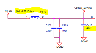
Firstly DCDC4 of TPS65218 is connected 0.1uF and 47uF, it is working correctly.

Then, output capacitances(11 x 22uF) are added near the AM4372 for VDDSHVx, DCDC4 coudn't start up.

The other outputs were fell down.

By changing to one 100uF instead of 11 x 22uF, DCDC4 couldn't start up.

Could you please see the waveform below , and advise the two questions.

Ch3(pink): 1.8V(LDO1)

Ch1(blue): 1.5V(DCDC3)

Ch2(light blue): 3.3V(DCDC4)

(1)According to the datasheet P.14, output capacitance of DCDC4 is recommended 40uFmin, 80uFtyp and 100uFmax.

Does this means output capacitance should not exceed 100uF?

On the other hand, Table 5-10 of AM4372 datasheet, it is recommend to connect eleven 10uF caps for VCCSHV1~11)   

processors.wiki.ti.com/.../Am437x_gp_evm_3k0006_schematic_rev1_5b.pdf

(2) What is the reason of not power up correctly and a measure?

---

I appreciate your great help in advance.

Best regards,

Shinichi

  • Shinichi,

    There are 11*10uF distributed capacitors in the AM4372 EVM schematic. Each 10uF capacitor is shown very close to the point of load. For example, C221 is placed near to VCC of MT29F4G08AB on the schematic. The schematic does not show 11*22uF capacitors, so you should not use.

    And you say you test with 1x47uF + 11*22uF = 289 uF total >> 100uF max. This is too large.
    11*22uF = 242uF by itself is too much.

    Schematic do not show 47uF or 100uF at output of DCDC4. It shows 10uF.


    The AM4372 team designs and validates the EVM/EVK that is using the 1x10uF at DCDC4 output and 11*10uF distributed capacitance. Because the AM4372 processor team spends a long time validating their design, I recommend your design follow the PDF link you share in your question:

    10uF at DCDC4 output, 11*10uF at distributed points-of-load.
  • Hi Brian,

    Thank you for your reply.

    As you mentioned, I also think output capacitance should follow the EVM.

    I'll make the customer try 10uF at DCDC4 and 11x10uF at each load.

    I appreciate your great help.

    Best regards,

    Shinichi

  • Hi Brian,

    I send your comment to the customer, he has an additional question.

    I would be grateful if you could advise.

    ---

    I confirmed the URL

    processors.wiki.ti.com/.../Am437x_gp_evm_3k0006_schematic_rev1_5b.pdf

    The total load capacitance of V3_3D : 47uF+10uFx19+4.7uFx1+3.3uFx3+0.1uFx13+0.01uFx78=260uF

    DCDC4(TPS65218) could drive very large capacitance.

    It seems to be the same our board capacitance.

    What reason can be considered of not powering up properly?

    ---

    I appreciate your great help.

    Best regards,

    Shinichi

  • Shinichi,

    If customer refer to C415 as 47uF capacitor, then it should be noted that there is a Ferrite Bead (FB10) in front of this capacitor. A ferrite bead is a high frequency current "choke" with some resistance resistance, essentially a low pass filter that is slowing down the current into 10+47uF of current. 

    If customer have a 10+47uF cap that does not have a FB choke in front, this is a non-negligible difference.

    The same is true for C273 (after FB11), and C383, C391, C388 (after FB20 as V3_3AUD).

    The result would be 47uF+5*10uF = 97uF less capacitance this is instantaneously drawing current from VDCDC4.

    Has the customer considered the effect of the Ferrite Beads already?

  • Hi Brian,

    Thank you for your reply.

    I understand when the ferrite beads are connected, the inrush current of the output capacitor can be mitigated.

    I checked the customer's connection, there are ferrite beads the same as EVM.

    So I ask him to change the same capacitance(10uF) and check.

    If he has an additional question, I consult again.

    I appreciate your great help.

    Best regards,

    Shinichi

  • Hi All,

    Just want to confirm that in my system (TPS65218 and AM335X)  I had a similar power up issue at the output of DCDC4. My waveforms were basically identical to Shinichi waveforms. 

    I solved the problem by reducing the output capacitance at the output of DCDC4. 

    Salvo

  • Thank you for the confirmation, Salvo!