This thread has been locked.

If you have a related question, please click the "Ask a related question" button in the top right corner. The newly created question will be automatically linked to this question.

WEBENCH® Tools/TPS63020: Confirmation of application circuit for TPS63020

Part Number: TPS63020

Tool/software: WEBENCH® Design Tools

Hi, 

I have a query regarding application circuit of TPS63020. I have found different application circuit in datasheet and the design generated by TI web-bench designer.

Please find the below images for reference

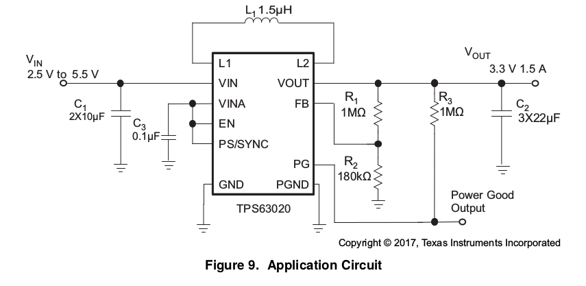
          ( Typical application circuit from datasheet)

Design generated form TI web-bench designer

Input parameters given for TI web-bench designer: V in= 3.6 V to 5.5 V, Output: 5 V, 1.5 A

In both the circuits, different number of input and output capacitors and different value of inductor are suggested. 

Please help me in which application circuit has to implemented

Also please tell me know what difference will I get in performance w.r.t two designs

Thanks in advance.

  • Hi Sai,
    The input capacitor seems to fine in both the cases. Regarding the output capacitor the webench recommendation is sufficient, but using higher capacitance helps to reduce output ripple, and less voltage drops during load transients.
    For the upper resistor of the feedback divider (Rfbt) I would recommend not to use a higher value than 1Mohm.
    The inductor is fine in both cases.

    What is the end application?
  • Can you tell me how to simulate load transients in TI web bench designer ?

    Please suggest me a value for feedback divider (Rfbt)
  • It can easily be done by going to the "Sim" tab at choosing load transient on webench.
    Please take a look at section 8.2.2.5 of the datasheet to calculate the feedback divider.