This thread has been locked.

If you have a related question, please click the "Ask a related question" button in the top right corner. The newly created question will be automatically linked to this question.

TPS3808-Q1: design review (schematic)

Part Number: TPS3808-Q1
Other Parts Discussed in Thread: TPS3890-Q1

Hi There,

I appreciate there is more than one TI part here, but I am keen to understand if the TPS3808-Q1 (please ignore the EVM part number in the schematic) would work here as a delayed switch to set the LDO to 4V. I will also include the thought behind the rest of the circuit to help give some system background.

The LDO (TPS7B6701) in question is powered from 12.25V (PFC1_VCC2).

The IC, U204 will switch to 4V after 200ms. The LDO is not active until 1 second when the PFC1_VOUT is higher than the threshold.

The LDO RESET signal will be pulled up externally and connected to a micro for additional control.
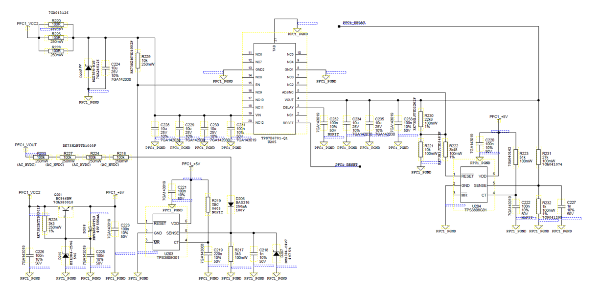
Many thanks in advance for your help with this.

Ross


  • Hi Ross,

    I looked over the schematic and I believe the LDO output will be roughly the ADJ voltage (1.23V) when SENSE is low because /RESET is pulled "low" due to undervoltage condition at SENSE which would then put R222 in parallel with R221 which would change the Vout voltage based on the new resistor divider to roughly 1.23V. When SENSE goes "high", /RESET will go "high" after the delay and then remove R222 from the resistor divider setting Vout to roughly 4V. My only concern is what will happen during power up before the minimum operating voltage (<1.7V for TPS3808-Q1 and <1.5V for TPS3890-Q1) in which R222 will appear disconnected and Vout will appear to be 4V during that time. Is that the intended operating? U203 looks to be configured correctly but the /RESET pull-up voltage should remain within the recommended operating conditions which is <6.5V for TPS3808-Q1 and <5.5V for TPS3890-Q1 but looks like /RESET is being pulled up to PFC1_VCC2 which is 12.25V so too high. Let me know what you think.

    -Michael