This thread has been locked.

If you have a related question, please click the "Ask a related question" button in the top right corner. The newly created question will be automatically linked to this question.

UCC24612: for 60V 3kW LLC rectification

Part Number: UCC24612
Other Parts Discussed in Thread: UCC256303

Hi all,

My customer  tied UCC24612-2 for LLC cct. sec. rectification with use aux.wire.

First 160ns Vgs is 9.5V and next it down to 6V.

Output voltage is 60V so aux.wire used.

But 3kW high wattage required big parallel Mosfets which Rdson is 7mohm,

and need high Vgs for lower Rdson.

Vgs 6 V is too low to keep MOSFET's lower Rdson.

This result in lower efficiency rectifier.

Is there some method to keep high efficiency such a high power MOSFET required high Vgs.

Thank you.

  • Hello Doi-san,

    Thank you for your question. I'll take some time to compose an answer and reply again in a little while.
    It will be helpful if you can tell me: does the output stage of this LLC use full-bridge or half-bridge rectification?

    Best Regards,
    Ulrich
  • Ulrich-san,

    Full wave rectification. Using two UCC24612-2 and each drive two 7mohm 200V? MOSFET in parallel.
    If you know 6V drive FET(Si ,SiC,GaN), it's also solution.

    Thank you,
  • Hello Doi-san,

    The gate-drive function of the UCC24612-2 (as well as -1 version) uses a proportional gate-voltage adjustment to actively regulate the SR MOSFET drain-to-source voltage to about -50mV.  This technique allows the controller to detect when Vgs starts to dip rapidly while trying to keep Vds = -50mV at low drain current.  In turn, this allows the controller to turn off the MOSFET(s) very quickly and prevent reverse conduction.

    However, since the SR Vds is regulated to -50mV, it is useless to reduce Rds(on) to an extremely low value because the gate-drive will simply lower Vgs until Vds = 50mV for most of the conduction interval.  3kW at 60V means 50A average output current.  Using 50A as an example, 50mV/50A = 1mR resistance.

    A set of MOSFETs in parallel with Rds(on) less than 1mR will be regulated to operate at the equivalent of 1mR.

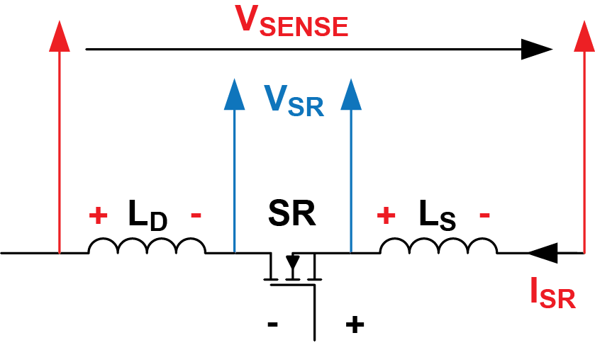
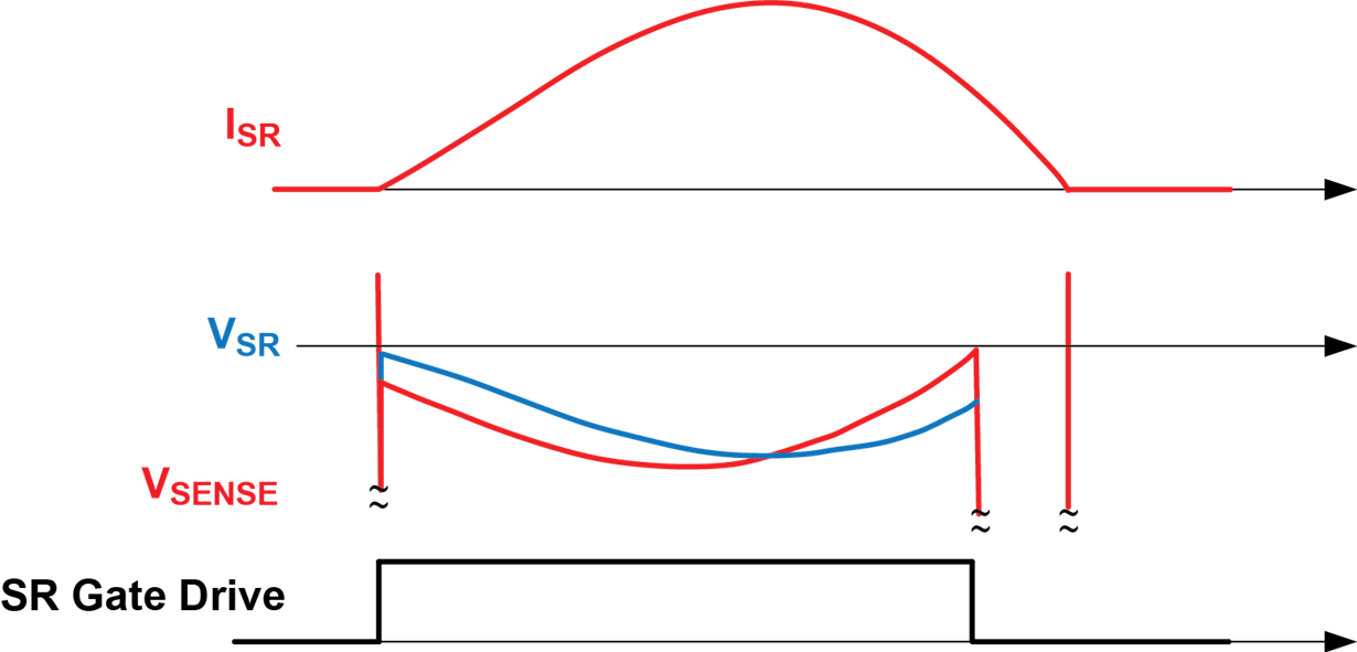
    Significant overdesign to achieve 0.1mR, for example, will not be fully effective.  Initially, turn-on will be driven at Vgs = 9.5V for a time.  The proportional gate drive is enabled only after a falling current slope is detected.  However for this power level, I suspect that large package devices (Such as TO-220 or TO-247) are used.  These larger devices often have high parasitic lead inductance, which prematurely triggers the turn-off threshold due to the falling di/dt (see diagrams).   This too-early turn-off can be a significant contributor to excess loss in the SR.  


    For high-power LLC applications, here is an idea that may be able to avoid early turn-off from the effects of package and parasitic inductance.   Obtain some UCC24612-1EVMs from the TI Store on our website.  These EVMs can be placed in parallel with the existing MOSFETs in your application and biased from the Aux windings.   It uses a smaller MOSFET with 19mR on-resistance and 150-V rating in an SMD package with very little inductance.  Because the EVM Rds(on) is much higher than the LLC SR MOSFETs, a smaller portion of the output current will flow through each EVM.  The EVM controller gate-drive output must also be connected to the LLC MOSFET gates, and disconnect or remove the LLC SR controllers.

    Now the EVM controller can detect the SR voltage only on the smaller EVM MOSFET without significant distortion from parasitic inductance and it should significantly reduce early turn-off of the LLC MOSFETs and improve efficiency.   If this experiment works well, please consider to use the technique for the LLC application.  It will require using an SMD MOSFET with negligible package inductance on the PCB, in parallel with the existing 7-mR FETs.  If it is impossible to add SMD FETs to the board, maybe FETs in an IPAK package can improve things.

    Best Regards,

    Ulrich

  • Ulrich-san,

    Thank you.

    Do you can find out SMD MOSFET which typical Rdson is =or< 3.5mohm and Vds =or>200V ?

  • Hi Doi-san,

    I searched Infineon, ST-Micro, and On-Semi websites.  Only Infineon has a wide selection of devices, but not all ratings are in SMD packages.  
    Infineon has a 6.6mR, 200-V device only in TO-247, which has high lead inductance.   No SMD.

    Why use 200V for a 60-V output in full-bridge configuration?  Can 150-V parts be considered, or even 100-V parts?  There are many more possibilities with SMD packages at lower Rds(on).  Also, Infineon has a 3.9mR, 100-V logic-level part in D2PAK (this package has no Drain inductance but still has ~5nH of Source inductance).   They have several selections in 1.5~9.3mR range in low-inductance packages at 100-V and 150-V ratings at 10V drive levels.

    Please see their Product Catalog at this link:  https://www.infineon.com/dgdl?fileId=5546d4625607bd13015621522aa012cb  pages 83 to 87.  
    Their D2PAK-7-pin package will have lower source inductance from many leads and bond wires in parallel.  Otherwise, the SuperSO8, DirectFET, and TO-leadless (TOLL) have the lowest package inductances.

    Regards,
    Ulrich

  • Ulrich-san,

    You can calculate the required voltage for the FET by using this.
    UCC25630x Design Calculator (Rev. B)
    For 60V output, over 150V MOSFET should be selected.
  • Doi-san,

    I checked the UCC25630x calculator and it is set up to calculate for center-tapped output winding and half-bridge rectification only. It does not calculate for full-bridge output. I'm not sure what parameters must change for a full-bridge output: I am not an expert on LLC.

    In a full-bridge rectifier configuration, the SR FETs see only the maximum output voltage. There may be a little ringing overshoot from stray inductance, but normally the reverse voltage of each SR FET (or diode) is fairly well clamped to the output voltage. For 60V output, you can even use 80-V FETs, if the peak ringing is well-snubbed.

    I think you can find better MOSFETs for your application in the 80V-100V range, even logic-level.

    Regards,
    Ulrich
  • Ulrich-san,

    I do not said Full-bridge, it is full wave rect.

    You can understand the difference by,

    electronics-tutorials.ws/diode/diode_6.html

    And actually my customer use TO-220  150V  7.5mohm max. MOSFET.

    And customer carefully checked your pointed inductance issue, but the result is NO.

    This phenomenon can be explained by only the theory for this IC.

    Anyway, If we cannot find a MOSFET, which is TO-220, 150V 7.5mohm max. and low Rdson at Vgs=6V,

    Can you find it ?

    If not, UCC24612 cannot to be used for not-full-bridge LLC rect. output = 160V 3kW( big current).

    My customer used another maker's and got good result.

    Thank you,

    H.DOI

  • Hi, Doi-san,

      Thanks for the information.

      The voltage drop down to 6V is the feature of the IC that trying to speed up the turn off and extend the conduction time.

      As Uli mentioned in the earlier email, the large parasitic inductance causes the voltage drop above the turn off threshold and often ends up with earlier turn off SR. Once the SR is turned off, the SR conduction voltage is its body diode forward voltage drop and it causes much higher conduction loss.

      In this IC, instead of keeping the full SR driving voltage, the driving voltage is reduced to 6V and keeps going lower to regulate the sensed drain to source voltage at -50mV. By doing so, the MOSFET will have higher voltage drop as you mentioned. However, this help to extend the SR conduction time to avoid the body diode conduction, because the increased MOSFET voltage drop could make driver IC see more negative voltage and keeps the SR FET on. The increased conduction loss ends up reducing the overall conduction loss because of less body diode conduction.

      If we use the full driving voltage on the SR MOSFET, even though it will have less conduction loss when the MOSFET is on, because of earlier turn off, the body diode conduction could increase much more conduction loss. It ends up to have worse performance.

    Bing

  • Bing-san,

    Do you try 60V 3.3kW S.R.?

    Immediately Vgs down to 6V.

    No use at normal Vds 150V MOSFET  - which Rdson @ Vgs only 10V  spec sheet.

    Thank you,

    H.DOI

  • Hi, Doi-san,
    Can you show some waveforms?
    UCC24612 doesn't allow the proportional gate drive to kick in until second half of the conduction time. In your case, you should not see it goes down immediately.
    Here are couple questions.
    1. Do you have a resistor from MOSFET gate to source? The IC has very weak pull up capability after initial minimum gate pull up time of 250ns. If you have a resistor there, you need to increase the resistor value to above 100kohm or remove it
    2. For the 6V portion, is your gate drive conducting a long time after that, or it turns off immediately after the voltage drops down to 6V
    3. How is your REG pin voltage? Is it at 9.5V or 6V?
    We never tried the IC at the 3kW level. However, based on your Rdson of 7.5mohm, the IC is able to handle the Rdson pretty comfortably.
    Thanks.
    Bing
  • Bing-san,
    It takes long time to hear you.
    My customer already gave up and remove this.
    He is now busy to evaluate UCC256303 and he can't do it.

    Thank you,
    H.DOI