This thread has been locked.
If you have a related question, please click the "Ask a related question" button in the top right corner. The newly created question will be automatically linked to this question.
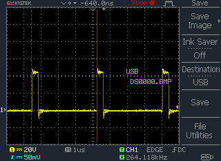
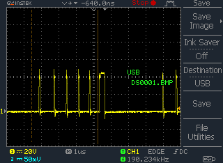
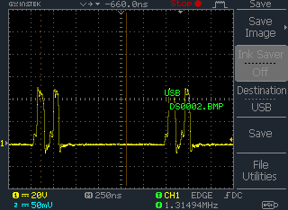
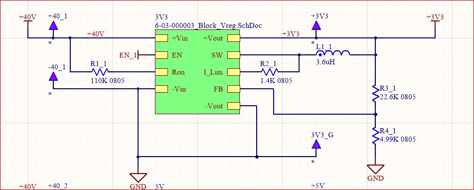
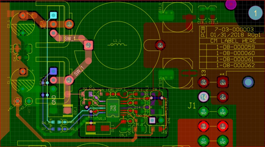
I'm testing my 3.3V 10A buck regulator that uses the LM3150 and I noticed that my High Side Gate signal looks good up to 5A than i starts to have a small dip/drop during he cycle, see screen shots below. Any guidance as due to the cause would be great. The 1st picutre is a screen shot of the gate signal below 5A. The second 2 are different gate signals oveserved above 5A.
I have 300uf on the output, I have a mistake in my part information in altium, My calculations show that I need a minimum of 220uf I would assume I have enough on the output.
I'm looking at the Alternate ripple injection section of AN-1900 how do you caclulate the vaules of Rr,Cr and Cac? When I add anything to this node or to Cff the ouput no longer regulates to 3.3V using the resistor values found using Vout=Vfb x (Rfb1+Rfb2)/Rfb1.
Hi,
I normally follow this equations for calculating the Ripple injection portion of it
How to design a stable Fly-Buck™ converter with COT (Part 1)
Thanks
-Arief
I used the formulas found in the referenced materials and I still have a stability issue, when I add Rr=10k, Cr=.01uf and Cac=0.22uf it changes my output voltage from 3.3V to 4.5 - 4.8V (not stable) as well as the switching frequency goes from 300kHz to 430kHz. I didn't see any of this during my initial testing with a resistive load, I then moved it to power my PCB and saw that my upper FET was at 140°C after 10 minutes and started to probe with a scope. I now have the instability issue with a resistive load also, is there a chance the IC is damaged?