This thread has been locked.

If you have a related question, please click the "Ask a related question" button in the top right corner. The newly created question will be automatically linked to this question.

BQ24297: USB communication does not work when chip D+ and D- are connected

Part Number: BQ24297

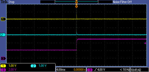
If we have the BQ24297 connected to the USB  OTG bus, we cannot connect another device.  If we make the connection between two USB devices (enumerate a device) and then connect the BQ24297 D+ and D- lines, the USB connection continues to work.  

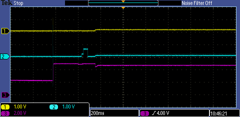
If we wait the one second for the BQ24297 to finish its data detection, it seems we cannot use the USB communication after that time.

We have tried this with the chip in our circuit, and also with the BQ24297-EVM board. The result is the same.

Please give any insight on what to look for ?  Thanks

  • Hey Harry,

    Harry Bissell said:
    If we have the BQ24297 connected to the USB  OTG bus, we cannot connect another device.

    Can you explain this a bit further? Do you have a block diagram to highlight the test conditions you have? Is the OTG device another bq24297 device? 

    Harry Bissell said:
    If we make the connection between two USB devices (enumerate a device) and then connect the BQ24297 D+ and D- lines, the USB connection continues to work. 

    So what you're saying is that if VBUS is plugged in, and then you apply the D+D- lines later to the charger, the USB communication continues to work?

    Do you have a schematic of how you are connecting the D+D- pins to your system?

    Regards,
    Joel H

  • Thanks Joel. Our system uses an iMX6 processor board. The USB OTG port is connected to a micro USB connector that serves as a charging port
    for our system (working) and also to communicate with an external PC (not working). On the PCB, the USB OTG data lines have three points on each net, the iMX6 OTG port, the microUSB, and the D+ / D- connection to the BQ24297. Our first test was to cut the traces to the BQ24297, which allowed the USB to communicate properly. Following the ideas on the forum, I tried inserting 100 ohms series resistance between the BQ data lines and the USB OTG, it failed like a direct connection did.

    I made and external USB "Y" cable, paralleling all four lines (+5V, D+, D-, GND) so we could test further. If we connect a USB device (such as our iMX6 evaluation board to the PC, the USB serial communication works fine. If I add the BQ24297 to the connection (either our PCB with only the BQ24297 connected (no iMX6), or your BQ24297-EVM board by plugging in the "Y" cable, the communications are not interrupted (works).

    If I connect the BQ24297 first to either the iMX6, or the PC, the communications do not work (cannot enumerate any device on USB).

    I can send schematic pages but they will be hard to follow, they represent a "Y" cable, in essence.
  • When the BQ24297 is on our system board we can talk to it via I2C and check any registers etc. When I hook up the BQ24297-eVM we cannot access I2C, but the charge light comes on when we connect the PC, so we think it is working correctly. The BQ24297 otherwise does what we expect in identifying the proper charge current limits etc.
  •  Photo of the "Y" cable.

  • Hey Harry,

    My thought here is that when the iMX6 board and the bq24297 charger are present together, enumeration may be trying to start while our charger is also trying to detect.

    Is it possible to capture a scope plot of the D+ line, D- line, and the VBUS voltage or USB source to the charger triggered on when the input source appear? This is good timing/logic level check for the USB communication, because we always want the D+/D- lines to be HIZ from the iMX6 side while the charger is running its input source detection. Until that detection completes, I would wait to enumerate the USB port.

    The schematic would help me track net names to follow what is connected to D+/D- on our charger and around it.

    Another option may be to step up that series resistance to the charger to like 200 Ohms. Its a safe value that should not break the USB BC1.2 detection.


    Regards,
    Joel H
  • Hi Joel. I tried the 200 ohm resistors, they did not work. I suppose they would be more effective for signal integrity issues, not the problem we
    seem to be having. I'm attaching the schematics. The "A" "B" "C" pages are the connections to a SolidRun SOM Solo (iMX6). I will set up the oscilloscope plot in the morning and send it as well.

    The "host" in our case would the the PC, and the iMX6 is a slave device. I think the host is what would initiate the enumeration, please let me know if I'm correct about that. I don't know what triggers the enumeration and how to delay it if this is the case. I'm thinking I might try
    opening the D+ and D- lines, let the BQ24297 see the incoming power from the PC USB connection, then connect the data lines after one second.
    I think that would force the delay I want to try... but I hope the solution is more elegant than that (hopefully something in software...)

    Thanks again
    Harry
  • CH1 & 2 are D+ and D-, CH3 is USB Power from PC. iMX6 power is off.

    Same as above, but now the iMX6 power was already on when the USB power from PC was applied

    Same as above, iMX6 running, connect to PC USB

    Same as above, iMX6 running, connect to Battery Charger (no USB Data)

  • Hi Joel, In your earlier reply you said we should wait to enumerate until the BQ24297 has had time to run its detection. I don't know
    how to control when the PC tries to enumerate the USB device. Any ideas?
  • Hey Harry,

    A few notes to your previous questions and comments:

    As I understand it, the host device (PC USB) waits for enumeration from the slave device (iMX6) in your case. This is a handshaking started by the device that plugs in such that the port

    And as you said, the problem may not be an signal integrity issue. Moreso, it may be a timing issue.

    From the scope captures, I also have several questions:
    Capture 1/4: The D+/D- lines seem to rise up to float up to some value. In this test, are those lines (USB_OTG_D_P and USB_OTG_D_M in your schematic) floating as well? This is where the iMX is powered off, so I assume the D+/D- lines are floating.

    Capture 2/4 and 3/4: What is the difference between these two tests? The test conditions sound very familiar, where the iMX is already running, and then PC power is applied, but there are two different waveforms I see. Is there something different between iMX already powered on and iMX already running?

    Capture 3/4 and 4/4: These look almost identical. That blip on Capture 3/4 on the D+ line is the typical waveform seen during D+/D- detection on the charger. Is Capture 3/4 with the charger present as well?


    Regards,
    Joel H
  • Hi Joel

    Capture 1/4 is with one end of the USB cable plugged into a PC (host) and then plugged into our circuit with the power supplies off (except for the BQ24297 which has the battery voltage applied. The trigger is the rising edge of the +5V from the USB (PC), the data lines as shown. I'm can't say for sure if the iMX6 is "floating" ie. Hi-Z or if (because it is unpowered) it presents some parasitic load.  

    Capture 2/4 and 3/4 differ only in the time base of the oscilloscope. You can read it from the screen. Capture 1/4 and 2/4 are 4ms/div, Capture 3/4 and 4/4 are 200ms/div. I wanted a longer view in case something interesting happened after the initial connection.

    Capture 3/4 is with the iMX6 running (powered on) and then connected to the PC. the connection timing is the rising edge of trace 3.  Capture 4/4 is the same condition but the power is a USB wall-wart charger, which provides the 5V charging voltage to the system but has no active data lines.

    We have as an interim fix cut the D+/D- runs to the BQ24297 and left them floating. This allows the iMX6 to use the USB port correctly, but the fix is less than completely acceptable. The BQ24297 detection is limited to 500mA in this condition.  I also tried cutting the same runs and shorting the D+/D- pins at the BQ24297, which makes the chip detect all chargers as "non-standard" and allows higher current (2A) but we fear that might overload some PCs.

    The right solution is to have the BQ24297 run as TI intended it to run...   Let me know if you can suggest any additional test condition I can try. Thanks again for your support.

    Harry

  • Hi Joel. I can be reached at 248-702-6600 x307 if that is more convenient for you. It might be faster to talk about the issue. Thanks
  • So Harry,

    2/4 and 3/4 have the iMX running, and the bq24297 not connected.

    4/4 has the iMX running with no USB data and the bq24297 connected.

    Do you have a waveform showing the behavior, where you have USB communication and the charger running?


    Regards,
    Joel H
  • 2/4 and 3/4 have the iMX running and the BQ24297 connected
    4/4 has a charger (with no data lines) connected and the BQ24297 connected.

    I'm going to try connecting the PC and the BQ24297 without the data lines connected and the iMX6 running, then connect
    the data line to the BQ24297 and iMX6 at the same time. My thought is that the BQ24297 will see the USB +5V go high and do its detection
    routine, then after that I'll try to establish the data connection.

    I'll set up the scope shot you requested now
  • Thanks Harry,

    Yea I just want to see the test scenario that causes the behavior you originally asked about, so I can look at both D+ and D- lines for incorrect behavior.


    Regards,
    Joel H
  • Hi Joel:

    I did some more tests with our board without the iMX6, and the TI BQ24297-EVM board.  I added the 200 ohm resistors in series with the data lines. Then I tried to connect to a simple USB memory stick.  That enumerated correctly if I plug in the Stick, then the BQ24297, OR if I connect them together and plug into the PC at the same time. SO that works as we would expect it.

    Then I tried a samsung tablet, using the same setup. I also worked if the connection was made to the BQ24297 first, or second... as in the memory stick case.

    The same tests all work with our circuit board, with the iMX6 removed.

    When I add the 200 ohm resistors on our board, (or disconnect the BQ24297 on our board and use the EVM with 200 ohm resistors) and try and enumerate the iMX6, it fails every time (does not recognize the USB device).

    I tried re-creating the original scenario, where we connect to the iMX6 first and add the BQ24297 after, I have not been able to duplicate it every time. Once in a while it works, usually connecting the BQ24297 causes the connection to fail. I was trying to get that "scope shot" you requested but have not succeeded. If I buffer the PC output with a powered hub, it seems a little more reliable. That is not a reasonable use case for our product, and we don't know what the hub does for us. I think maybe the connection between the PC and the hub is more robust, and does not drop as easily as connecting right to the iMX6.

    Seems like I might be barking up the wrong tree... the problem seems to be related to the iMX6 enumeration, and not with the BQ24297. 

    Now we are stuck, as we don't know what is different between the memory stick, the Samsung tablet (except maybe that they have much more sophisticated firmware?) and the iMX6

    Any ideas ?  Thanks

    Harry

  • Hey Harry,

    The enumeration of the iMX6 side may very well be the issue. 

    Do you have a scope capture of just the iMX6 enumerating? A time scale of like 400ms/div or 1s/div would be good to see when everything starts.

    One thought would be to power sequence the iMX6, forcing it to wait until our charger's detection completes. The test case here would be plugging in the bq24297 and then connecting the iMX6 device. Even a USB switch could help in this scenario, physically isolating the D+/D- between the PC and charger and the PC and iMX6. This does require some control mechanism, but it is a viable solution.

    Regards,

    Joel H

  • Hi Joel

    I made a little progress... On our unit, with the iMX6 connected and the BQ24297 data lines with 200 ohms in series... the unit will connect and enumerates correctly ~if~ I have a USB hub in series with the USB connection from the PC.     (the hub is bus powered).  

    PC > HUB > iMX6 and BQ24297.

    Which begs the question... what is it about that the hub does that makes this work ?    We have had some connection issues with some computers to the iMX6 directly that will not connect unless we go through a hub. Other PCs work OK without the hub. 

  • Hey Harry,

    Sorry for my late response. 

    I am not exactly sure what about the iMX6 would cause an issue like this, apart from some bus enumeration failure. However, without experience with this device, I cannot say for sure. The USB Hub may also act as a sort-of buffer between your platform and the PC. I imagine USB Hubs have their own enumeration process with the PC USB port, as there are typically Hub port controllers that Mux the PC USB to the individual Hub USB ports. 

    Again, I will point to the same suggestion of adding in a USB Switch between the PC and your system, such that you get PC USB ---> USB Switch --1--> bq24297 and PC USB ---> USB Switch --2--> iMX6

    Regards,

    Joel H

  • Hi Joel: Well... I know :^) We finally traced the problem down to an issue with the USB data bus itself. We reused an earlier design that had
    a 90 ohm common mode choke on the data lines, and two 33pF capacitors to ground on the inside (our board) of the choke. This always worked
    in the past, however we only connected it to lower speed devices in those applications. Take off the 33pF caps and it works as it should. So the earlier thought... it is not the BQ24297 is correct, but probably cutting the lines to it reduced the overall (marginal) capacitative loading. Likewise using the USB Hub acted as a buffer and allowed enough drive to overcome the losses. At 480MHz (480MB/s) the loss with the caps is about 18dB... We were just on the edge of operation. We are deleting the capacitors from the design. What that does to EMI may be another story.

    Thanks so much for your support. Having someone to trade thoughts with is a real boon in troubleshooting.
    Harry Bissell
  • No worries Harry. I'm glad you guys were able to get it figured out.

    And at the end of the day, the response here will help some other system designer looking through the forums for the answer to a similar question, so thanks for reaching out.

    Feel free to reach out again if any more questions come up.


    Regards,
    Joel H