This thread has been locked.

If you have a related question, please click the "Ask a related question" button in the top right corner. The newly created question will be automatically linked to this question.

TPS22958: TPS22958 Transient thermal response

Part Number: TPS22958

Hi TI,

TAMB(MAX) (°C) = 70
Load Switch TJ(MAX) (°C) = 125
Load Switch RϴJA (°C/W) = 67
PD(MAX) = (TJ(MAX) – TAMB(MAX)) / RϴJA (W) = 0.82089 W (for this part)

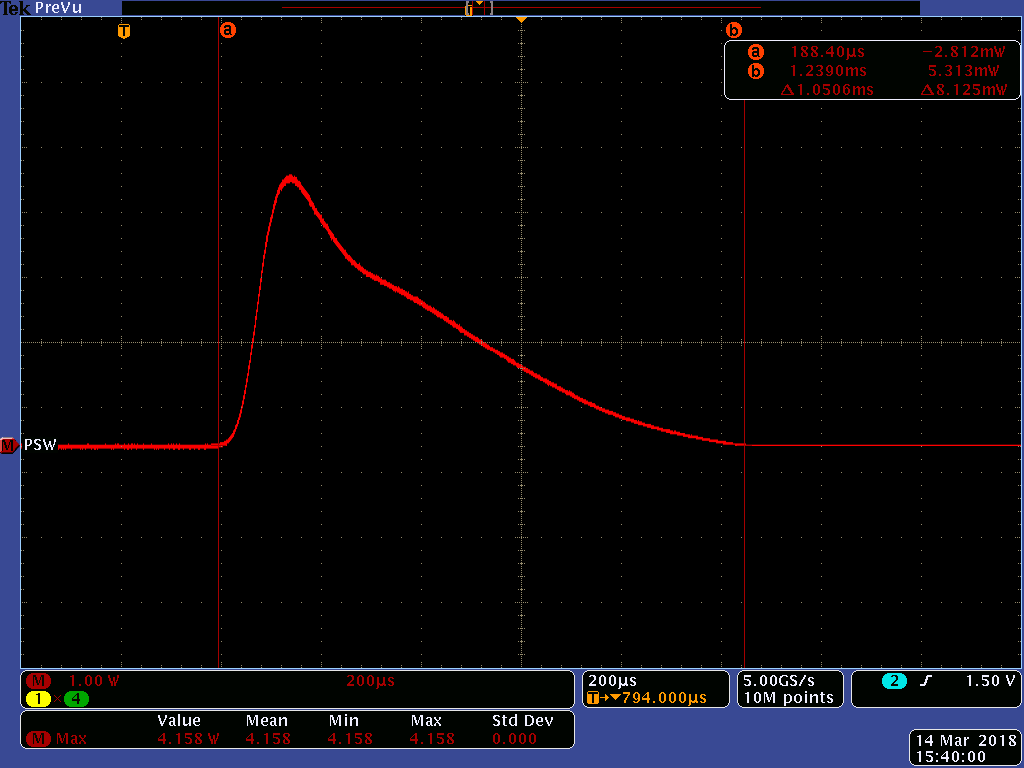
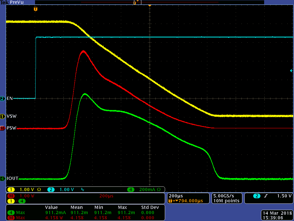
Our design evaluation measured value (refer System 5V High Side Switch_b6c.png in the attachment)
Turn on Time Window, T = tEND - tSTART (ms) = 1.05
Total Energy Transferred in T (mJ) = 1.59
Constant Power Pulse, P = E / T (W) = 1.51

SOA Confirmed via P < PD(MAX) is No.

For that could you please share Transient thermal response curve (transient thermal resistance vs time) for TPS22958 part.

Thanks
Sathiyan

  • From Garph VSW is VIN-VOUT and PSW is VSW*IOUT
  • Hi Sathiyan,

    If I am reading the scope shot correctly, then VSW is the voltage across the switch (VIN-VOUT), and you are multiplying IOUT and VSW to create the PSW curve. Thank you for your detailed analysis here, it makes it clear as to exactly what you are seeing.

    While I do not have the transient thermal response curve for this device, I can let you know that from a transient thermal perspective there is no concern with your application. For your 1ms rise time, the device would even be able to handle the full 4A/6A load (depending on the package) as inrush current.

    Thanks,

    Alek Kaknevicius

  • Hi Sathiyan,

    In general, for our load switch devices, we do not generate transient thermal response curves (transient thermal resistance vs time). What we can do is verify specific use cases to make sure they are acceptable for the device. Based on the pulse you showed, our team does not have any concerns with your application. It is well within the acceptable parameters of the device.

    Thanks,

    Alek Kaknevicius