This thread has been locked.

If you have a related question, please click the "Ask a related question" button in the top right corner. The newly created question will be automatically linked to this question.

TPS61170: TPS61170 has too big noise on Vout

Part Number: TPS61170


Dear sir,

I bought TPS61170EVM-280 and checked Vout under the following configuration.

Vin = 10.8V

Vout = 24V (original setting)

Iout = 0.1Adc (electric load)

Only use TPS61170EVM board (no connect with USB control)

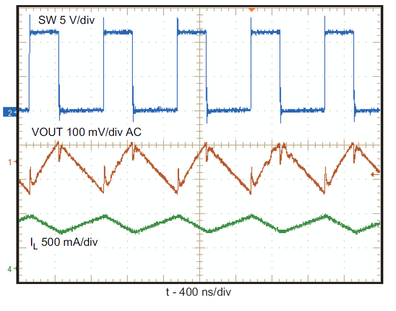
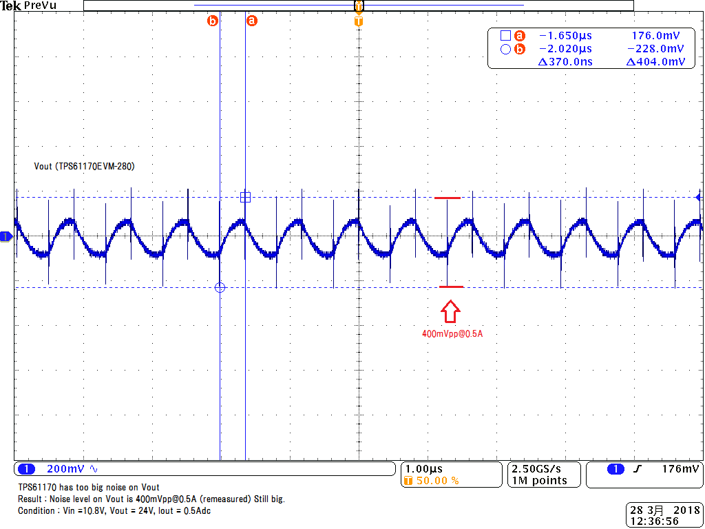
And I found the issue that TPS61170 has too big noise on Vout which looks like no relationship with SW-node.

The noise level is about 570mVpp (too big). Please see the attached waveform and give an advice.

  • How did you test it? The ripple should be tested across the output cap with very small loop.
  • I checked the ripple across the output cap with small loop on TPS61170EVM-280.
    I would like to know how much ripple(actually spike noise) across the output cap on TPS61170EVM-280 as reference.
    Could you give the sample waveform on TPS61170EVM-280 for me?
  •  The output ripple should be looked like following with 20MHz band width.

  •  The way how to test the output ripple: make the probe away from the inductor, or the SW noise will coupled into the probe.

  • Hi Helen,

    Thank you for your pics. It's very easy to understand.

    And sorry for your inconvenience, the ripple level as you captured is no problem.

    My point is the spike level as picture below. It's 400mVpp@0.5A load as original EVM.

    Is this noise level within device spec?

  • What is the bandwitdth you used during the test? Is it 20MHz?  if the bandwidth is big, then the tested noise will bigger because of the high frequency coupling. Could you please take a photo of how you tested it?  Because the location of the Cout and the SW is very close.

  • Hi Helen,

    Thank you for your reply.

    I do not use the bandwidth filter when I measure the switching noise (not ripple noise).

    Because the noise frequency is usually **MHz, so if I use it, the switching noise will be gone.

    Here is my condition to test it.

  • Thanks for the update. Its clear now.

    If you use a very high bandwidth, then the high frequency noise is easy to be coupled into the test probe. So if you insist to use high band width, then use an external board away(>20cm) from the SW node of the TPS61170 EVM  board.  add a 1uF small cap on that board, then test the ripple again.  the noise coupling effect will getting better.

    Could you please share the customer information with us. Please accept me as friend.

  • Hi Helen,

    Thank you for your reply.

    I understand the spike noise will be decreased when I take the EVM board away from the SW node of the TPS61170 EVM board.

    If so, I'm worried about the emission noise from the SW node. That's why I plan to capture this spike noise near from the EVM.

    It sounds like there is another way to measure the spike noise from the SW node, not use oscilloscope.

    Could you tell me how to measure emission noise from switching DCDC converter normally?

  • There's a standard on testing the EMI, like CISPR22. But as far as I know, EMI generally means far field coupling instead of the near field couplling. it is tested 3m or 10m away from the power supply.

    But what you tested is very close to the SW node. any power converter's SW node, no mattter how good, if it has dv/dt, which=Vsw/trise or Vsw/Toff, it can coupled into the probe through the parasitic cap. so the nearer the probe close to the SW, the higher the coupling effect.

    So please use 20MHz bandwidth to test the real ripple. or the test result is not accurate.