This thread has been locked.

If you have a related question, please click the "Ask a related question" button in the top right corner. The newly created question will be automatically linked to this question.

UCC28064: 90VAC Single Phase Operating Condition

Part Number: UCC28064
Other Parts Discussed in Thread: UCC28063

Hello
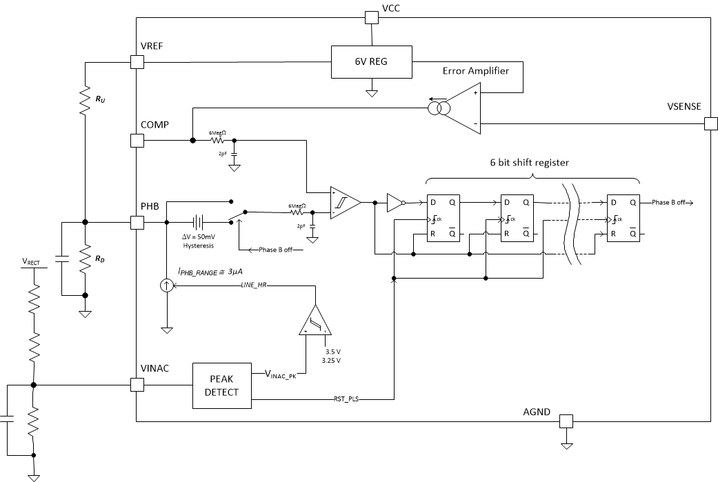
My client is currently working on a new project with UCC28064. 300W input is being designed. The problem is that the overlapping phase appears in 28063.

As far as I know, I heard that ic was improved for the same phase in 28064, is not it?

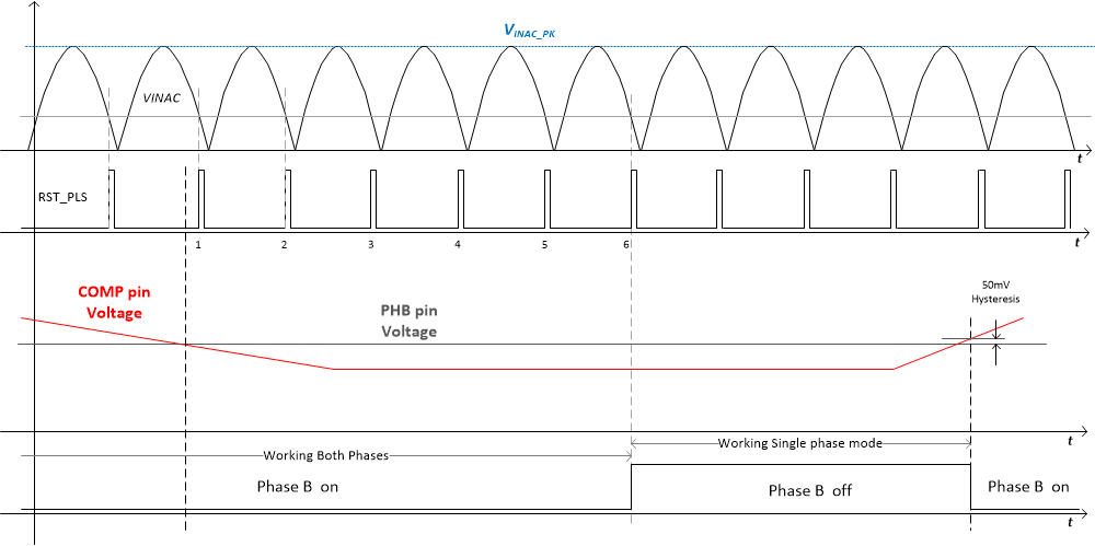
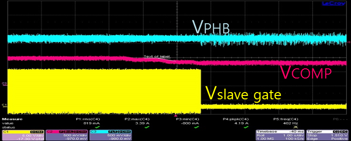
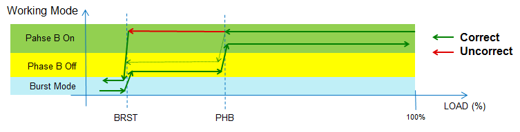
Another problem at the moment is AC264V, which operates in one phase under light loads as shown in the datasheet. However, as shown below,

90V does not match the contents of the datasheet. Which part should I refer to?

  • Hi Andy,

    The Phase Shading Function in UCC28064 was changed respect UCC28063.

    In UCC28063 you have to decide with external circuits when turn on or off phase B and provide the suitable logic signal.

    In UCC28064 there is more intelligence inside the IC. You just need to set a threshold.

    In UCC28064, the COMP pin voltage is proportional to load. The IC just compare COMP pin voltage with the Voltage of PHB pin to decide if the phase B has to on or off. You can feed to PHB pin a voltage threshold through a simple resistor divider connected to VREF pin.

    Of course the comparator that compares COMP pin voltage with PHB pin voltage has an Hysteresis (50mV Typ) for noise immunity.

    To further improve noise immunity also a time filtering was added.

    Additionally at high line the PHB pin source a small current (3uA typ.). This makes that at high line [180VRMS; 264VRMS] PHB voltage is higher.

    I'll try to resume here below:

    1. set a resistor divider from VREF pin to fix PHB Voltage so PHB pin Voltage = PHB1 = (R2 / (R1+R2))*Vref

    2. Assuming low line [90; 132]; if V_COMP pin Voltage crosses PHB1 From High to low, and V_COMP stay Below PHB1 for a time higher than around 3 line cycles Phase B is turned off.

    3.  Assuming low line [90; 132]; if V_COMP pin Voltage crosses (PHB1 + Hysteresis) from Low to High Phase B is turned on immediately.

    4. at high line [185; 264] the Threshold is no more PHB1 but PHB2 =  PHB1 + (R1//R2)* 3uA.

    Here below the Block diagram of the Function.

    - The 6 bit shift register with the RST_PLS signal that provides one clock pulse every Line half cycle are used as time filtering.

    Here below the relevant waveforms


    Here below the waveforms that clarify differences between Hi line and low line:


    Here below the wave forms that clarify differences between High line and low line

  • hi

    Vcomp is lower than Vphb as shown below when power is turned on with low load at 90VAC input as shown below. In this case, I think that Phase B is turned off.

     However, Phase B is turned on as shown in the figure below.

    The load must be further lowered to turn off the phase. Why is Phase B turned on when Vcomp is lower than VPHB when the power is on? Is this normal?

  • Hi Andy,

    What you are describing is an IC bugs we have already identified and will be fixed in the final version of UCC28064.

    We are sampling device to customers but device is not yet released to market.

    With reference at the picture here above.

    - Assuming at the beginning full Load conditions: system has both phases on (starting from right in the picture).

    - Gradually decreasing the Load: COMP pin Voltage decreases

    - When COMP pin Voltage goes below PHB pin Voltage, Phase B should Turn off and it doesn’t.

    - Further decreasing Load System enters in burst mode and starts operates in single phase mode.
    -Increasing again the Load, Only Phase A is switching and Phase B is off even if out of burst mode (Correct)
    -Further increasing the Load, when COMP pin Voltage exceeds PHB pin Voltage Phase B is turned ON (Correct)
       
    The problem is an incorrect clock provided to the shift register in the block diagram I reported in the first picture.
    You can see the correct behavior if the line frequency is below 20Hz.
    We are going to fix this issue and the final version of the IC will work properly.
    I think this answer your question.
    Let me know if my explanation was clear enough and if you need more details.
    Regards
    Davide