Part Number: UCC29910AEVM-730
I'm stuck on what seems like a really basic problem in understanding this EVM. I hope I'm not just being a dope.
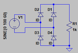
It looks to me like the only way the EVM would work as intended is if "ground" (the solid black triangles) is allowed to float, not at earth ground or line Neutral potential. The D5 bridge rectifier would produce a full-wave rectified AC across e.g. C5, but only if the bottom anodes track the negative half-cycles of the line. If TP6 were connected to earth ground by, say, the bias supply at J1, you'd only get a half-wave rectified signal at C5.
This would also put the negative half-cycles of the AC line on J1 and J2 with no external bias supply connected, which doesn't seem safe.
And what is the relationship of the output voltage to earth ground and the line? It looks like TP13 (+) is connected to the AC bridge high side and TP12 (-) is regulated negatively from there. This would mean that a voltmeter between TP12 and line Neutral (~earth ground) would show some significant voltage, and the output is referenced to line hot rather than ground.
It seems like the grounding issue would be fixed if the EVM were driven by a line isolation transformer and the black triangle node was grounded, but the output voltage would still be referenced to the line high side rather than ground. The AC input is labeled Line and Neutral though, so it doesn't look like that's what is intended.
Can somebody set me straight?