Hi,
I am a second year student and I was using the LM3671MF-3.3NOPB device to output 3.3V for a system with typical load 70mA with bursts up to 400mA. However, the device we're using is outputting a significantly lower voltage under load, ie 2.5V instead of 3.3V with a 100mA resistive load applied to it. There is audible coil whine. The device seems to fail after a short while, developing a short between the output and the ground and pulling a lot of current. Without any load, the output is a perfect 3.33V.
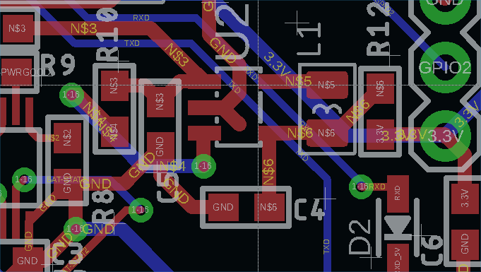
Since I am a student and beginner PCB designer, I was hoping I could get some pointers on why my design is not behaving properly. Here's the PCB layout as well as the component IDs of the passives used:
The passives used were GRM188R60J475KE19D 4.7uF input capacitor, GRM188R60J106ME47D 10uF output capacitor, DFE201610E-2R2M=P2 2.2uH power inductor.
I have tried putting an additional ground connection closer from the chip to the capacitors with a wire (where the missing GND trace is on the PCB) as well as adding more capacitance on the output, however this has not helped.
Any feedback and advice would be greatly appreciated.
Thank you very much in advance,
Sincerely,
Tomasz Bialas


