This thread has been locked.

If you have a related question, please click the "Ask a related question" button in the top right corner. The newly created question will be automatically linked to this question.

UCC256301: UCC256301 LCC design

Part Number: UCC256301
Other Parts Discussed in Thread: UCC27517A, UCC27517,

Hi  

Currently we have a 1000W project is based on the PFC+LLC architecture.

There are two questions. Can you help us?           

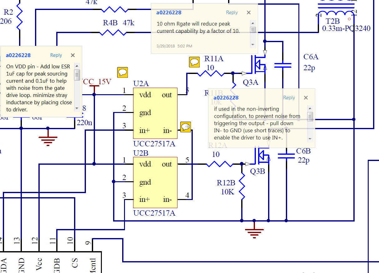
1. Whether UCC27517A VDD is connected correctly or not? (such as an attachment)         

2. If we want to change to LCC architecture. Whether or not there is a LCC tool can help us design the circuit.

What is the difference between the sampling circuit of LCC and LLC and how to determine the LCC sampling capacitance parameters?

Thank you.

PFC+LLC design.pdf

  • Thanks you for your interest in our product. I will review your questions and get back to you.

    V.A.

  • We do not have a design tool for LCC yet. One question? What do you mean by sampling circuit and sampling capacitor?
  • Hi Jerry,

    Thanks for your question on UCC27517A. Im an apps engineer with this device and will help you out.

    See pic below with sch review. My notes are similar for the LLC as they are with PFC (below).

    For the LLC, IN- is connected correctly. what diode is D16 for highside 517?

    also, Can you tell me what fets and switching freq you are using?

    Thanks,

  • also I see that the output of the controller, which is a driver, is connected to the input of the 517 for the LLC stage. This will damage the driver because this controller has an integrated half bridge driver for the LLC therefore the 517 is not needed.

    Thanks,

  • Hi Jeff,

    We currently modify the circuit as below. Can you help to review it and suggest?

    517 Vdd is powered by auxiliary power.

    D16: 1A1000v trr 250ns

    Mosfet: IPX65R110CFD

    switching freq: 60k-120k

    Thank you,

    Jerry 

  • Hi Jerry,

    Thanks for your update,

    For VDD pin, every time a pulse happens on the output, the current supplied to OUT comes from the VDD pin. Therefore a bypass cap needs to be close to the device, TI recommends adding a larger cap of a few uF in parallel to the smaller one of about 100nF for supplying this drive current.

    For the bootdiode, a faster bootdiode such as MUR120 may be needed as the delay time to turn on the highside has to factor in the reverse recovery time of the bootdiode after each bootcap replenish.

    Also connecting the output of the LLC controller UCC256301 (which has >1A half bridge driver in it) directly to the input of UCC27517 might damage the device so a current limiting series resistor should be added to the inputs of ~100ohm.

    Thanks,