This thread has been locked.

If you have a related question, please click the "Ask a related question" button in the top right corner. The newly created question will be automatically linked to this question.

Sync-In/Sync-Out Pin assignment in UCD9248 datasheet

Other Parts Discussed in Thread: UCD9246, UCD9248

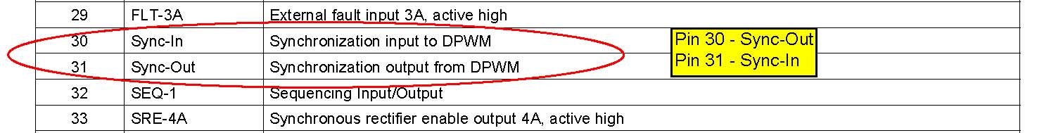
Hi. Pin 30 and 31 is assigned as SYNC-OUT and SYNC-IN in page 8 (pin assignment diagram) but is reversed in page 10 (pin description table). Which is the correct pin assignment? Thank you.

  • The Pin Description table on page 10 of the datasheet is in error, Pin 30 should be Sync-Out and Pin 31 Sync-In, see below.

    An errata document which will include this correction is in process and should be avaialable on the web shortly.


  • No errata is available for this part in the web site yet.

    Any other issues we should know about?

  • Hi Brad. Can you give some guidance for customers who have existing designs that have tied these pins incorrectly? I believe tha DS suggests pulling up the SYNC-IN pin and leaving the SYNC-OUT pin not connected. With this data sheet mistake, customers have reversed these connections resulting in SYNC-IN being left open. Is this OK? Thanks.

  • The hardware configuration guide indicates that a pull-up is required on the TDI/SYNC_IN pin under the JTAG Communication and Synchronization section.

    This should be clarified, in that, the pull-up is only needed to satisfy the TDI input, however on the UCD9246 both of the TDI and SYNC_IN functions are multiplexed onto the same pin.

    For the UCD9248, the TDI and SYNC_IN functions have seperate pins and only the TDI pin needs the pull-up.

    Putting an extra pull-up on the SYNC_IN or SYNC_OUT will not interfere with the operation of the device.