Because of the holidays, TI E2E™ design support forum responses will be delayed from Dec. 25 through Jan. 2. Thank you for your patience.

This thread has been locked.

If you have a related question, please click the "Ask a related question" button in the top right corner. The newly created question will be automatically linked to this question.

TINA/Spice/CSD18534KCS: High side N-Channel MOSFET not turning off / does not swing to 0V

Part Number: CSD18534KCS
Other Parts Discussed in Thread: TINA-TI

Tool/software: TINA-TI or Spice Models

Hi,

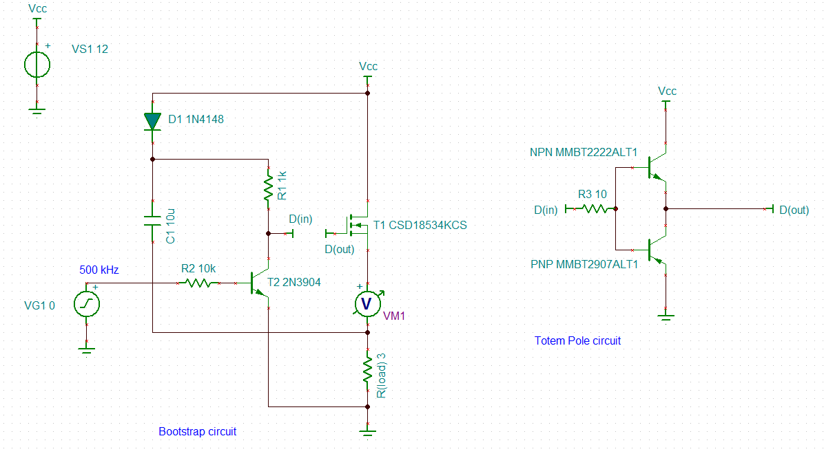
Below is a gate driving circuit for a high-side N-Channel MOSFET switch using discrete components.

This circuit consist of two seperate stages: a Bootstrap circuit (for boosting the gate voltage) and a transistor Totem pole stage for high speed switching.

This circuit successfully switches the MOSFET to 11.92V (Vcc = 12V) but I cannot manage to get it to discharge all the way down to 0V. The lowest I get it is: 3.94V.

VG1 is a 500kHz Sqaure Wave with amplitude: 2.5V, DC level @ 0V.

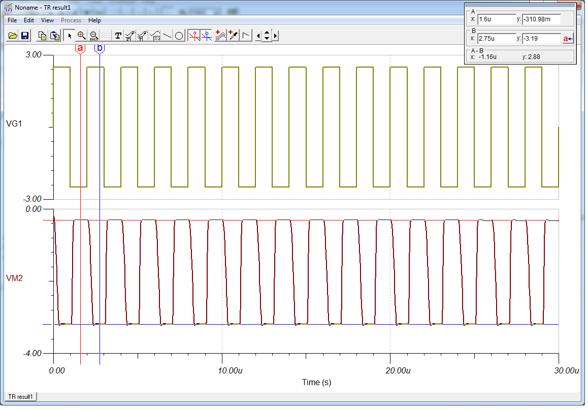
Below is the Transient Analysis for this circuit.

Can someone please assist with what the problem might be? It should be noted that I get the same results when switching at 100kHz, 200kHz and 500kHz (as well as frequencies well below 100kHz) so this doesn't seem to be the problem.

Any assistance would be greatly appreciated.

(Please don't suggest an integrated MOSFET driver IC as this would defeat the purpose :) ).

N-Channel MOSFET Driver

  • Hi Marius,
    Thank you for posting!

    Let me review this with some of our SPICE model experts and applications team. Hopefully, I can get back to you within 24 hours.
  • Marius,
    We are still looking into this. Could you probe the Vgs of the device under test and provide that waveform?

    Also, what is the value of Rload?
  • Hi Brett,

    Below is the transient analysis showing Vgs (graph VM2 below).

    Cursors "a" and "b" on the graph show the Max and Min of the Vgs waveform.

    R(load) is 3 ohm (as per the schematic). Therefore, this device should switch 4A @ 12V.

    Hope this helps.

  • Marius,
    Here VM2 looks identical to VM1 in the first waveform you provided. Can you double check that you are probing the gate to source of the FET or send the schematic of how you set up VM2 to measure? Thank you!
  • Hi Brett,

    VM2 has significantly different values than VM1. VM1 switches between approximately 12V (which is the supplied voltage) to 4V (but it should go all the way to ground - 0V, hence this post).

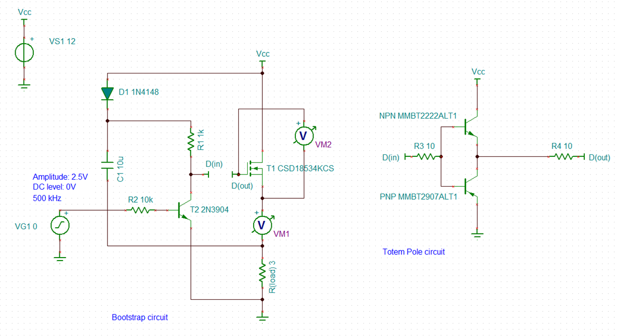
    Below is the schematic that shows VM2 (gate to source voltage, as you requested). Is this what you wanted to see?

    This output (VM2) switches between approximately -310mV and -3.19V (as per the cursors that I provided in my previous responce).

  • Marius,
    Sorry, I should have caught this right away. Could it be the problem is you have VM1 (in theory an infinite load) in series with R3 as opposed to in parallel with it? This is going to prevent any real current from moving through the FET, and makes everything else very difficult to predict.

    Were you trying to measure the voltage across Rload with this? If so, the voltmeter needs to be put in parallel, not in series with R3.
  • Hi Brett,

    Thanks for noticing this. I affected this change but the waveforms look even stranger now.
    I will play around with this a bit. Any circuit ideas that will successfully switch this mosfet from 0V to 12V at 500kHz?
    This did unfortunately not resolve my issue.
  • Marius,
    I understand. Sorry this didn't resolve your issue. Again, it was the first thing I should have noted - putting a voltmeter in series with the FET was bound to cause some very strange behavior.

    Feel free to send over your schematics and what the waveforms are showing now and I will take a look at it with our experts tomorrow.
  • Marius,
    Have you had any luck? Do you want to send over some waveforms, or do you want me to follow up with our apps engineers to see if they have an alternative suggestions?
  • Hi Marius,
    I haven't heard back from you in a bit. I know the suggestion I made did not completely resolve your issue, but without seeing some more waveforms and getting some guidance from you, I don't think there is much further we can take this on our end.

    As such, I am going to mark this thread "TI thinks resolved". If you have further questions, or you come back with some wave forms and have our team take another look at it, I would be more than happy to try to help.

    I believe once the thread closes, you still have 2 months to post and it will reopen.

    Thanks again for posting, and good luck with your design!