This thread has been locked.

If you have a related question, please click the "Ask a related question" button in the top right corner. The newly created question will be automatically linked to this question.

TLC5958: Multiplex issue, LED15 of module 0 sets LED0 of module 1

Part Number: TLC5958
Other Parts Discussed in Thread: TLC5957

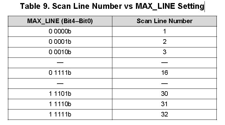
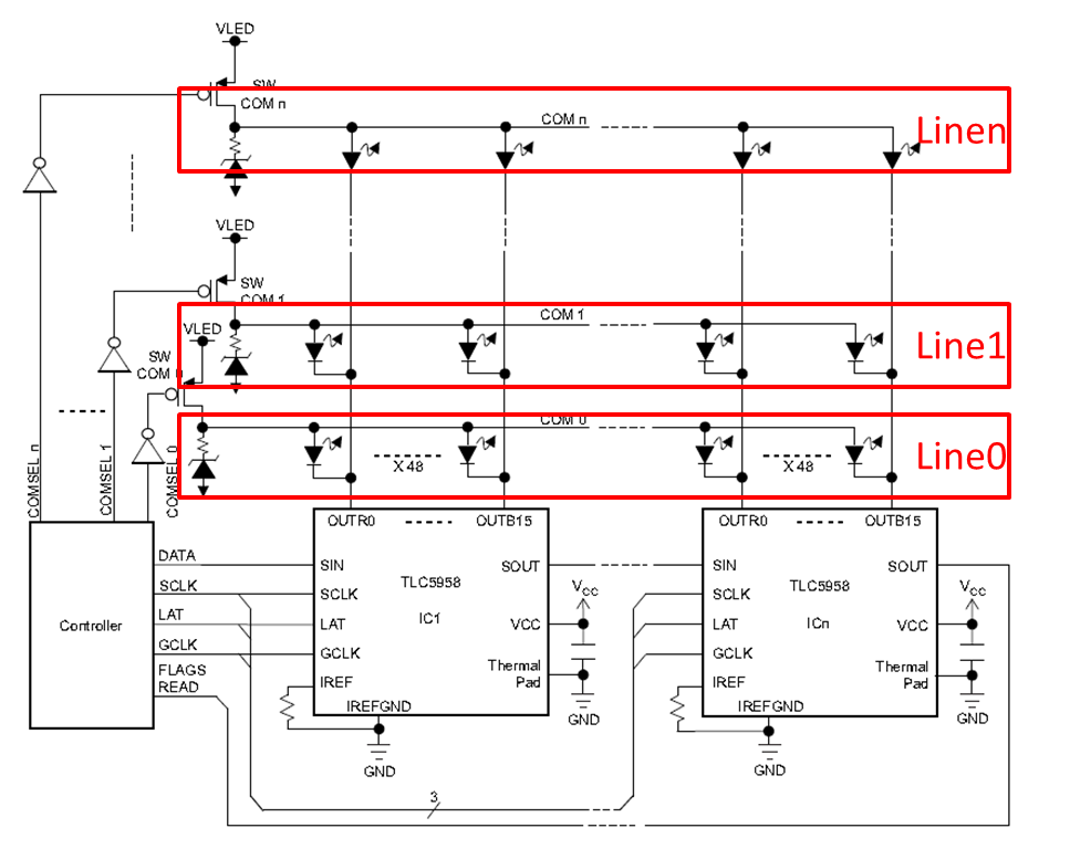
I'm using 2 TLC5958 chips (multiplexed) to control 32 RGB LEDs (setting MAX_LINE to 00001b).  

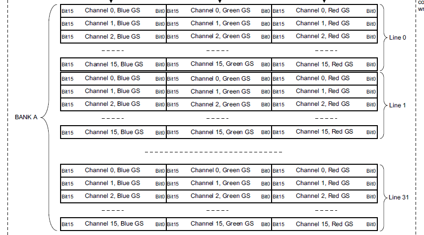
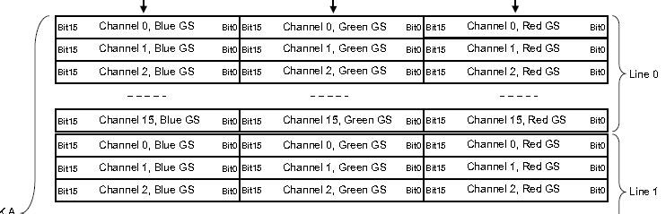
When I set values for channel 15 of first TLC5958, they also appear on channel 0 of second TLC5958.  After that, continuing to write GS Data, sets channels 1 thru 15 of 2nd TLC.

All FC settings are at their defaults except for MAX_LINE changed from 0 to 1.  

Any ideas what I am doing wrong?

  • Hi, David,

    Since you're using 2 TLC5958 to control 32 RGB LEDs, is there any reason to set MAX_LINE to 1?

    Does this happen when using MAX_LINE=00000b?

    Regards,
    Kenneth
  • Hi Kenneth,

    Thank you for your reply. The 2 TLC5958 are chained together (SOUT of 1st connected to SIN of 2nd) so that they can be set in a multiplexed configuration (exactly as the typical application circuit is shown in the datasheet). Setting MAX_LINE to 0 works fine when I only have a single TLC5958 connected controlling 16 RGB LEDs, but does not work with 2 chained together (for 32 LEDs). My understanding is that this is the exact reason why MAX_LINE should be changed to 1 (i.e. since now there are 2 lines/TLCs , 16 LEDs each, that are multiplexed for a total of 32 RGB LEDs). Please let me know if you think I am missing something here.

    Thank you,
    David
  • Hi, David,

    Multiplexing means using switching FETs to control more LEDs. By multiplexing, you can use 2 TLC5958 to drive 32*N(N is the line number) RGB LEDs.

    So in your case, line number is 1, and MAX_LINE=00000b should be OK.

    Do you send 2 TLC5958 data together and follow the 5 steps in the Application Report SLVA645:

    Build High-Density, High-Refresh Rate, Multiplexing LED Panel with TLC5958

    Regards,

    Kenneth

  • Hi Kenneth,

    Yes, I follow the 5 steps (where step 5 is inputting GCLK). I have SIN of 1st TLC connected to my controller (to input GS Data) and SOUT of 1st TLC connected to SIN of 2nd TLC. Hence, with them daisy chained I need to send a total of 32 RGB channels of GS Data. Setting MAX_LINE to 0 does not work (it only ends up setting 16 channels of 1 TLC), when I set MAX_LINE to 1, it works but has the problem of channel 15 of TLC getting duplicated onto channel 0 of 2nd TLC. Could this be a timing issue? Maybe something related to TD0 setting? I don't really understand the importance of TD0 or if this is something I should also change.?

    My understanding of MAX_LINE (based on the application note) is that it should be set to one minus the number of TLC5958 that are daisy chained together. This is correct understanding, right?

    Thank you,
    David

  • Hi, David,

    It's not correct about your understanding for MAX_LINE.

    As you can see from the Table 9 in SLVA645:

    MAX_LINE relates to scan line number, and scan line means you use MOSFET to scan. Although you use 2 daisy chained TLC5958, they control LEDs directly and you're not using MOSFET to scan. So the MAX_LINE is 0 because your scan line number is 1.

    TD0 should not be the problem and can you provide more infomation for me to identify the problem as following:

    1. Schematic of your application

    2. Do you input GCLK when doing step1-step4?

    3. What's your GCLK frequency?

    Thanks.

    Regards,

    Kenneth

  • Hi Kenneth,

    I have answered you questions below and provided some additional detail (including attaching a PDF here with schematic diagrams.

    [1. Schematic of your application

    My application actually uses 16 TLC5958 that are daisy chained.  I also use 8 dual P-channel MOSFETs to switch voltage amongst the 16 TLC5958s.  I did some tests with just 2 TLC5958 to try to narrow the problem, but did not make progress (this is why I initially mailed you with just the two TLC test case).  Attached here is the 16 TLC5958 design with MOSFETs, DMUX (for address line decoding), and LEDs.  

    2. Do you input GCLK when doing step1-step4?

    The GCLK is disabled while I initially write the GSData.  I wait several milliseconds before enabling GCLK after GS data write and VSYNC.  

    3. What's your GCLK frequency?

    8 MHz

    I also include a line to the file via drop box here: https://www.dropbox.com/s/2q0j564652m5vcx/HoloRGB_v24.pdf?dl=0

    Let me know if you have any new ideas or questions.

    Best regards,

    David

    HoloRGB_v24.pdf

  • Hi, David,

    I check the schematic and it is fine. GCLK is also OK from your description.

    For your original problem, it's more likely the GS data is not writen correctly. So please check your GS data write code to confirm LED0 of chip 2 is writen correctly.

    I'll also think more to find any other chance for such problem.

    Please let me know if you finish checking your code.

    Thanks.
    Regards,
    Kenneth
  • Hi Kenneth,

    I checked code and also looked at signals with my logic analyzer (see attached screen shot).  The code attempts to write colors to the first 18 LEDs, then set the remaining LEDs to off (RGB=0,0,0).

    It sets first 8 LEDs to Red, next 7 LEDs to Blue, next 1 LED to Green, next 2 LEDs Blue, next 236 LEDs are set to off.

    Results are 8 Red, followed by 7 Blue, followed by 2 Green, followed by 2 Blue.

    You can see in logic analyzer that Green write is not done any differently that red or blue writes (and color does not matter, even if I change all the colors, the effect is the same).

    It seems that with each additional TLC that is daisy chained, the number of "aliased" pixels increases by 1 (e.g. the 3rd TLC shows a blue then green LED, fourth shows 2 blue, then green LED, etc.)

    Logic Analyzer channels are set as follows (in attached screen)

    0. brown - SCLK 

    1. red - SIN TLC 0

    2. orange - LAT

    3. yellow - SOUT TLC 0 (SIN TLC 1)

    I am running out of ideas.  Let me know if you have any other thoughts.  Also, given my schematic, is it correct to set MAX_LINE to 15?

    Best regards,

    David

  • Hi, David,

    Firstly, since your scan line number is 16, it's correct to set MAX_LINE 15.

    One thing I want to check and confirm, as you can see from Figure 11, each WRTGS command writes 48-bit data, which is OUTBn/OUTGn/OUTRn(Bit15-Bit0), so you need 16 WRTGS commands to write one TLC5958 all channels GS data. Since you're using 2 chained TLC5958, your GS data should be writen like this: Chip 2 OUTB15-OUTR15(48bits)+ Chip 1 OUTB15-OUTR15(48bits), then one WRTGS command; Chip 2 OUTB14-OUTR14(48bits)+ Chip 1 OUTB14-OUTR14(48bits), then one WRTGS command;...;Chip 2 OUTB0-OUTR0(48bits)+ Chip 1 OUTB0-OUTR0(48bits), then one WRTGS command.

    And you need to send all 32 LEDs GS data together every time you want to change the GS status.

    Please check if you are using code like above.

    Thanks.

    Kenneth

  • Hi Kenneth,

    I believe the sequence you specify for writing GS data is inconsistent with the app note/data sheet. All channels in Line 0 (first TLC) should be written before all channels in Line 1 (second TLC), etc. as shown in excerpt below.

    As seen in prior logic analyzer screen, I am sending GS data in this precise sequence.  I also attach another zoomed in screen of data being sent for a single channel.  Again, everything I am sending seems consistent with the data sheet or app note so I still don't know what is wrong.  Is there anyone else there you might ask that has further detailed expertise on TL5958?

    Best regards,

    David

  • Hi, David,

    Sorry for the trouble you're facing now. Let's cooperate to solve it.

    I check all the information you provide and find that we have some misunderstanding for current application.

    1. Although you are using 8 dual-P MOS, you're not using multiplexing topology, and chip 0 is not line 0, while chip 1 is not line1.

    As you can see form the Typical Application Circuit in datasheet, multiplexing is usiing MOSFETs to drive Vled of each line, which is shared by all TLC5958 drivers:

    You can check with your circuit, you just use MOSFETs to control 16 TLC5958's Vled, which is not the same with above.

    In another word, I suppose you're controlling 16*16=256 RGB LEDs in total, if you're using 16 multiplexing topology, then only one TLC5958 + 8 dual-P MOSFET is needed.

    You can refer to the following circuit, it uses one TLC5957 + 5 Dual-P MOSFETs to drive 16*10=160 RGB LEDs.

    8765.TLC5957_10X16 RGB LED Matrix Schematic.PDF

    So your MAX_LINE sholud be 0 due to scan line number is 1. And you should connect all your Vled together because there's no need to switch Vled if you're not using Multiplexing.

    2.  If you remove you MOSFETs, or simple way to test, you switch ON all your MOSFETs, then you just have Line 0. The line in the following figure means you need to send all your GS data for 16 TLC5958 together since it's shift register inside. 

    3. If you want to check agagin with 2 TLC5958, please select the first two TLC5958, and turn off Vcc for the rest of drivers.

    Then you need to send GS data as I described in last post. Thus it should be OK.

    I'll request friendship with you on E2E so that you can send more results and get our suggestions.

    Thanks.

    Regards,

    Kenneth

  • I think this might be working! I did a quick test with just 2 TLC (as you suggest) and got a good result. I want to confirm it works in full 16 TLC design and then I will report back here and mark this thread as resolved. I might need a couple days since I am busy with other work here, but will let you know by the weekend. Thank you again for your help!!!
  • Hi, David,

    Glad to hear that it works.

    Please let us know if you need other help.

    Thanks.
    Regards,
    Kenneth
  • Hi, David,

    Any update for your latest result?

    I'll close this thread and if you have any more questions please reply to it directly and it will open again.

    Please help to click "Resolve" if the problem is solved.

    Thanks.
    Regards,
    Kenneth
  • Hi Kenneth,

    It definitely works now.  The key was you helping me realize that I did not need to raise LAT for a single pulse after every 48bits of GSData and that I could/should only raise LAT (i.e. the WRTGS) for the single pulse after all the GSData for all the chained TLCs was written for a single channel (i.e. 48 x number of TLCs - 1 pulses).  This was not clear from the AppNote I was reading since I think it was more focused on the multiplexing use-case.  Thank you again for helping me to get to a solution.  

    Best regards,

    David