


Hi,
We are facing issue in some of the samples of LM5117 that we have used in DC-DC converter whose rating is as given below-
Vin=18V - 32V, vout=13.5V and Iout=20A
Description of our control loop- We have designed external circuit such that LM5117 will regulate output voltage at 13.5V only when load current is more than 500mA. In no-load condition or with load current less than 500mA, UVLO pin of LM5117 is pulled low (0V) by a transistor, after which it looses its regulation and output voltage start decreasing. Once the output voltage reaches 9V,voltage at UVLO pin is released by the transistor (voltage at UVLO then is more than 1.25V) and converter starts regulating at 13.5V again.
Problem statement: In no load condition ,some of the samples are not behaving as per above description.
Behavior of Faulty sample: With load it is regulating at 13.5V. Once we remove the load UVLO pin of LM5117 is pulled low that forces it to loose its regulation and output voltage starts dropping. Once the output voltage reaches 9V, voltage at UVLO pin rises above 1.2V. After UVLO goes high, regulation should have resumed but in faulty board it's regulation is resuming when output voltage drops down to 5.6V.
Observed voltage in faulty sample at following pins when voltage is dropping from 9V to 5.6V-
1)UVLO- more than 1.25V
2)COMP- 4.76volt is observed at the output of internal error amplifier.
3) SS- Voltage at SS pin is also high (4.6V)
4) LO- We can observe that low side MOSFET is also turned ON to charge the bootstrap capacitor.
Having above mentioned observation on respective pins , LM5117 should have worked properly.
We are not able to understand why the IC is not regulating in some of the samples and what is that parameter that is forcing it to resume its regulation once it reaches to 5.6V. Please find below images captured in oscilloscope in faulty board and in healthy board.
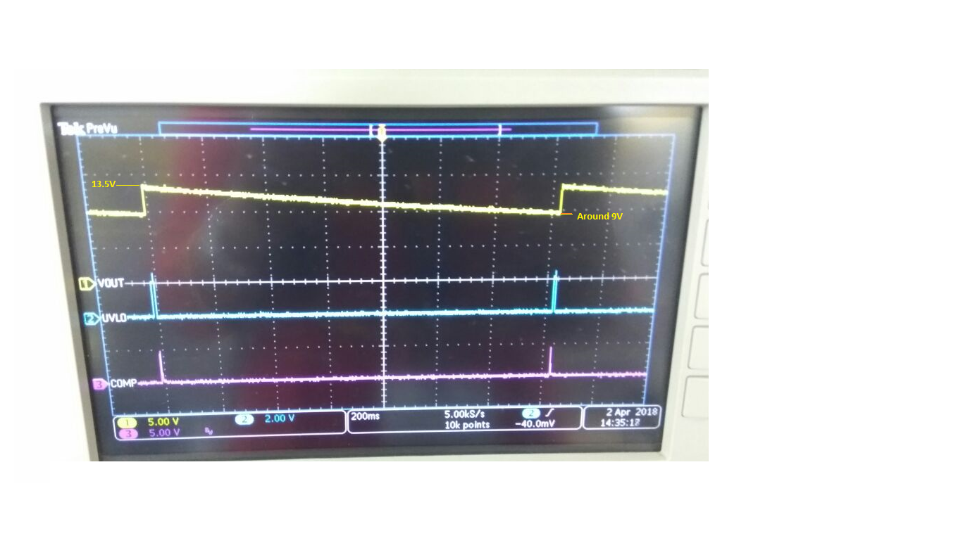
WF1# Waveform captured at Vout, UVLO pin and COMP pin in healthy Board-
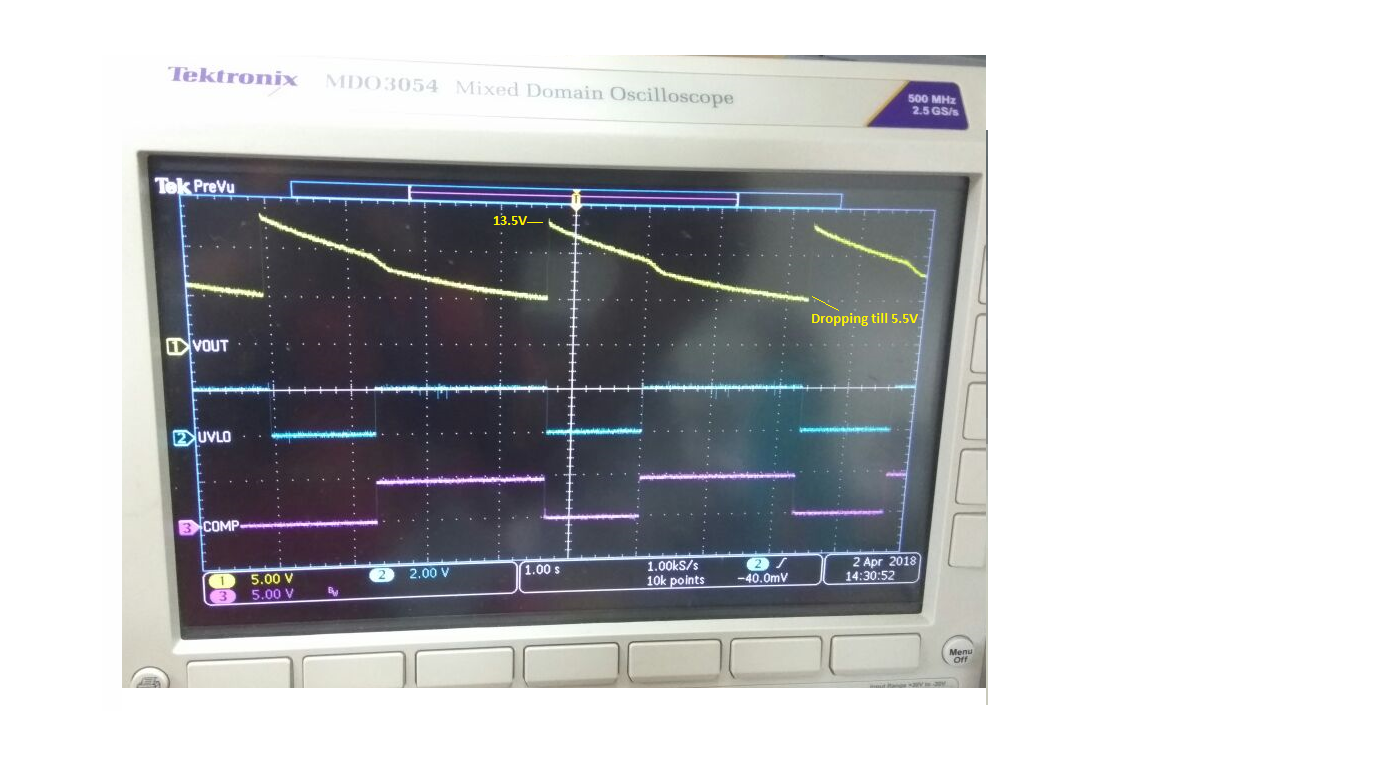
WF2# Waveform captured at Vout, UVLO pin and COMP pin in Faulty Board-
In addition to above observation-
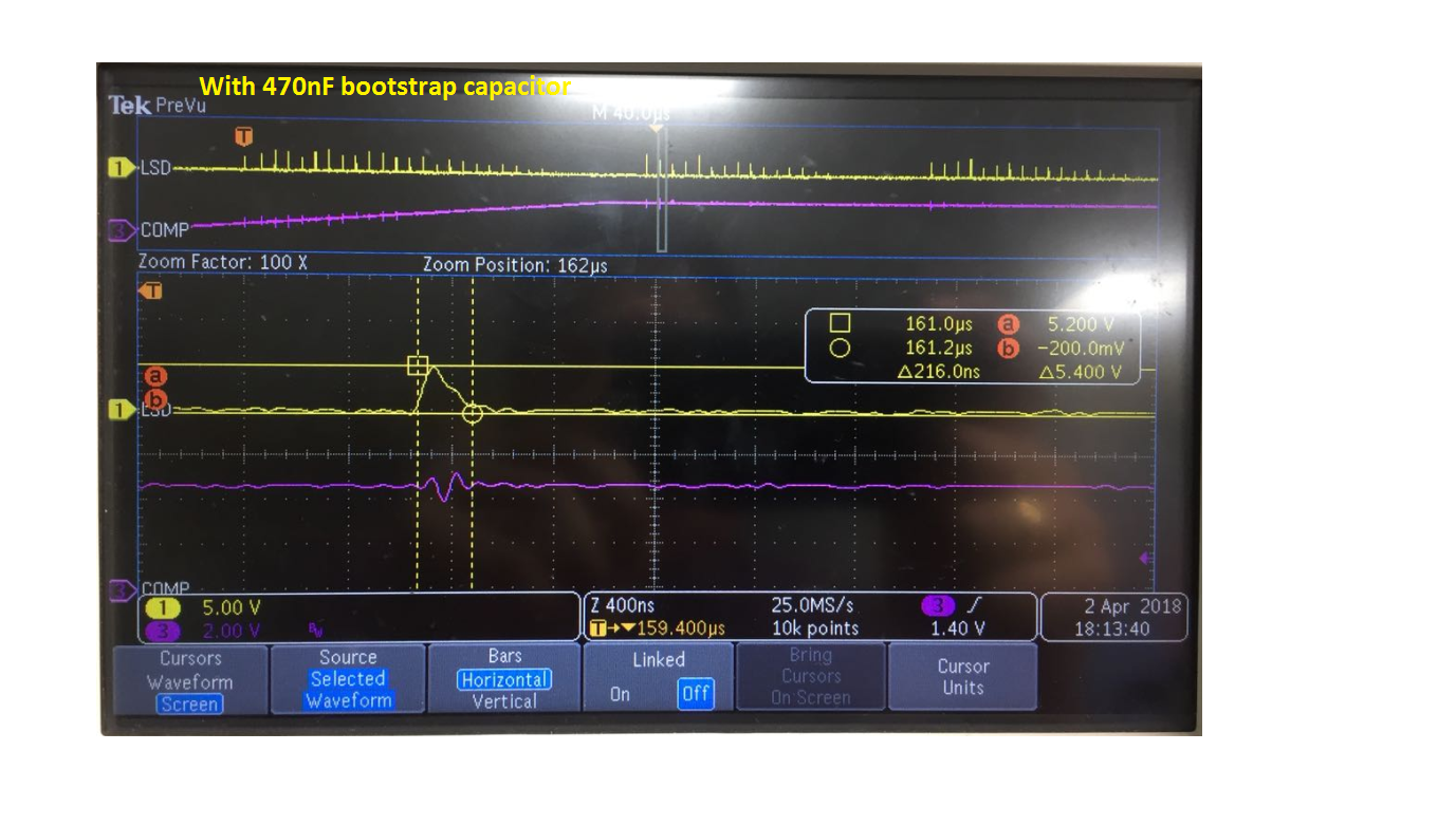
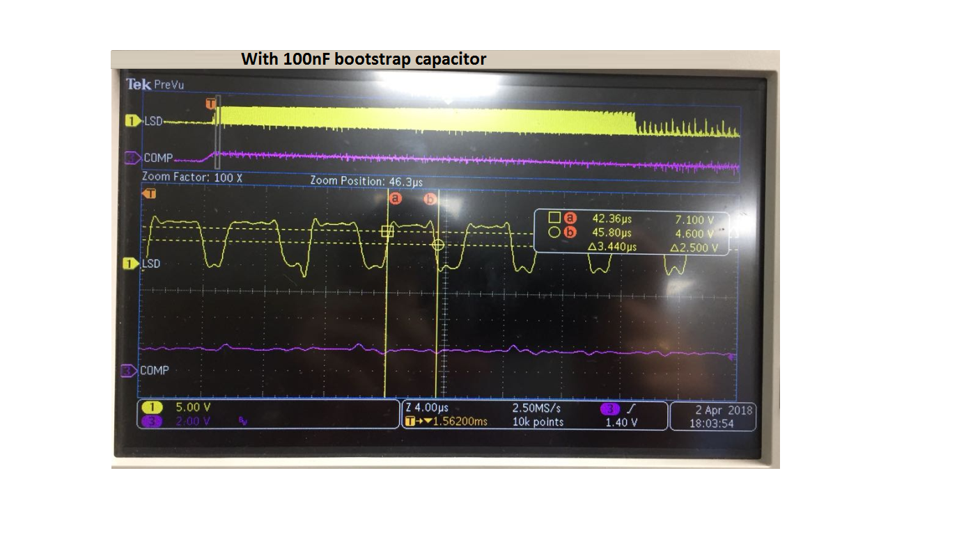
In our current design bootstrap capacitor is 470nF with which I checked the waveform at the gate of low side MOSFET. I observed that low side MOSFET is not turning ON properly .When i changed the value of bootstrap capacitor to 100nF, I could see proper pulses at the gate of low side MOSFET resulting in proper regulation. Can you please tell us what could be the reason of low side MOSFET not turning ON properly when the bootstrap capacitor is 470nF. In no load condition, which parameter decides the duty of low side MOSFET? Please find below the waveform captured at the gate of low side MOSFET and COMP pin with bootstrap capacitor 470nF and 100nF respectively.
I request you to answer my query as soon as possible.Thanking you in advance!

