Hello,
I believe there is a mistake in the datasheet of the UCC28950 PSFB controller.
Looking at figure 46 (at page 36 of the latest revision of the datasheet of UCC28950), one can clearly see that "D" and "C" driving signals are the ones commanding the leading leg of the PSFB.(leading leg is the one that provides the active to passive transition). In other words, the leg formed by transistors "C" and "D" is the leading leg.
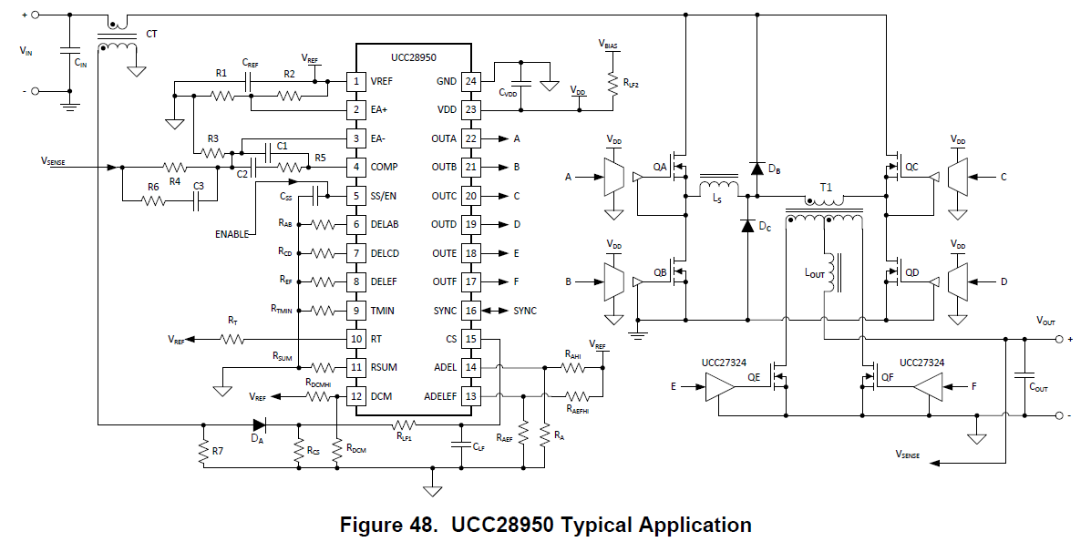
Then, I conclude that an improvement to the PSFB schematic (figure 48) can be made: swap places between Ls and T1.
Looking forward to your comments !