This thread has been locked.

If you have a related question, please click the "Ask a related question" button in the top right corner. The newly created question will be automatically linked to this question.

TPS65917-Q1: What is the maximum rated power of the PMIC chip (TPS65917-Q1)

Part Number: TPS65917-Q1

Hello TI Community,

Following is the part number of the PMIC chip I am using: TPS65917-Q1

Total calculated power requirement of my board from all the nodes are close to 500 mW.

I believe that this is way less than the total rated power of TPS65917-Q1. But I just wanted to confirm this against to exact rated power of TPS65917-Q1. But there is no total rated power or rated power per switch node information I could found in the datasheet. 

Could you please suggest the power information of TPS65917-Q1?

Regards,

Vishnu

  • Hi Vishnu,

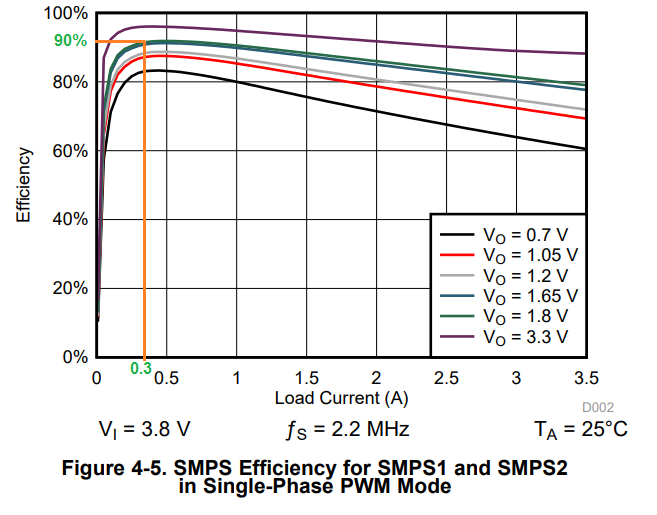
    For doing the power dissipation estimation, you can use the regulator efficiency curves in the datasheet and estimate the total losses inside the device. Once you have the device power dissipation, you can use the datasheet thermal information table (section 4.4) to estimate the junction device junction temperature using standard equation (Tj=Ta+(Rth*Pd). As long as device junction temperature, device ambient temperature (it is PCB temperature very close to device) and regulator max load currents are within our datasheet specification, it is fine.

    In your case, if the total device power dissipation is around 500mW, at ambient temperature of 105C, even considering RθJA (worst case), device junction temperature is below 125C and you should be good. If device power dissipation is much higher and if you think, you may have some thermal issues, you should do the detailed thermal measurements on your board to find out the actual junction temperature. Thermal parameters mentioned in the datasheet are for initial estimation only. Also please refer to the application note (SPRA953) mentioned below the datasheet thermal information table for choosing the correct thermal parameter mentioned in the datasheet.

    Hope this helps you.

    Regards,

    Murthy
  • Hi Murthy,

    Thanks a lot for the response.
    I understood the concept of the junction temperature rise.

    For confirming the maximum power loss in the device, Please go through following:

    Considering rail: 1.8 V
    Output current : 300 mA
    Efficiency = 90%
    Total input power = (1.8*300)/(0.9) = 600 mW.

    Please confirm.

    Regards,

    Vishnu

  • Hi Vishnu,

    You can follow the below equations to calculate the power dissipation:

    Overall BUCKx power losses including inductor losses:
    PD_BUCKx = Vout * Iout * ((1-efficiency)/ efficiency)

    Inductor power losses:
    PD_Inductor = Iout*Iout* R_DCR

    Power losses inside the device due to BUCKx:
    PD_BUCKx_device = PD_BUCKx - PD_Inductor

    You can calculate the power dissipation for each regulators and add them to get total ~ power dissipation of the device.

    You can also refer to the below application note for more detailed understanding. Since efficiency for the BUCK is already provided, you dont need to calculate the internal losses due to switching and conduction separately and it is already included in the efficiency data.

    www.ti.com/.../slva390.pdf

    Regards,

    Murthy
  • Thank you. This resolved my issue.