This thread has been locked.

If you have a related question, please click the "Ask a related question" button in the top right corner. The newly created question will be automatically linked to this question.

WEBENCH® Tools/TPS63070: Difference in TI webench circuit and application circuit in datasheet

Part Number: TPS63070

Tool/software: WEBENCH® Design Tools

Hello,  

I am designing power supply circuit using TPS63070.

My application requirements are as follows

Vin : 6V to 8.4 V

            Vout : 8 V

            Load current : 800 milli amps

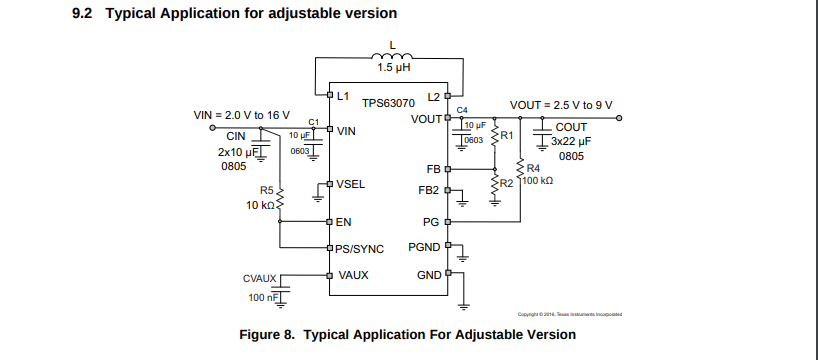
As shown in the below figure , Application circuit of datasheet is suggesting 10uF (0603) capacitor,  two 10 uF (0805) capacitors at input and 10uF capacitor(0603) , three 22 uF (0805) capacitors at output.

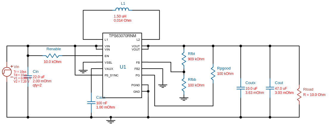
In contrast as shown in below image, TI webench simulation result is suggesting two 22 uF (1210) capacitors at input and 10uF (0603), 47 uF (1210) capacitor at output.

Please suggest pros and cons of both designs and also suggest the suitable design for my application as mentioned above.

  • both configurations are basically OK,
    the key thing is to have enough effective capacitance (recommended in the datasheet), considering the DC bias of ceramic capacitor.
    There is no upper limit for the output capacitance for this converter, with more capacitance the output voltage ripple and noise is reduced.

    In addition cascading capacitors gives you the possibility to readjust them and optimize their configuration in case your application needs better noise filtering.
  • Thanks for your reply. I am implementing the result from webench. In webench design I added extra 10uF input capacitor(0603) as it filters high frequency noises according to datasheet. Is it okay ?

    In addition to above change, I used capacitors as suggested in webench tool, except I am unaware of ESR and derated cap of the components. I ensured the passive component value, tolerance , temperature range and voltage rating are matching. How crucial role ESR and derated cap play ?
  • Yes you can start implementing this circuit.

    The ESR is causing the voltage output ripple so the lower it is the better for your application. because of the derating the effective capacitance left in the capacitor in reduced, therefor this need to be considered while designing
  • Hello Sabrina, 

    Thank you for your support.

    I will use capacitors with low ESR at input and output of the IC. I have a doubt regarding capacitor at vaux(3 rd pin)

    Recommended Capacitor at vaux by webench  : Cap= 100.0 nF , ESR= 1.0 mOhm , VDC= 6.3 V , Case code : 0402 , X5R, 10% tolerance

    But I am using  Cap= 100.0 nF , VDC= 6.3 V , Case code : 0805 , X7R , 10 % tolerance  . ESR value is not  available. How crucial is ESR value and case code for this capacitor?  Can I go ahead with selected capacitor and should I change it as recommended ? And kindly explain why ? 

    Awaiting your reply. 

    Thank you.

  • In this case the case size is more important. I f you keep the same capacitance value, smaller size capacitor have a higher self resonance frequency. I would recommend to choose a 0402 cap.
  • Can you please tell which properties need to be considered for choosing an alternative capacitor in this boost application circuit. I want to choose an alternate component because recommended passive components are not available in stock.

    And also in  webench report, properties of passive components in Electrical BOM and values in operating values at bottom of the report are mismatching.For example, Irms value of Cout capacitor is 4.59346 amp according to electrical BOM wherein Irms value of the same capacitor is given as 906.53 milliamps in operating values at bottom of the report.  

    Please tell the importance of properties in Electrical BOM and values mentioned in Operating values and which values need to be considered while selecting alternative passive component? 

    I am attaching the webench report for your reference.

    BuckBoost_1.6amp.pdf