This thread has been locked.

If you have a related question, please click the "Ask a related question" button in the top right corner. The newly created question will be automatically linked to this question.

TPS63021: Switching Noise from IC and Inductor Coil

Expert 2415 points
Part Number: TPS63021
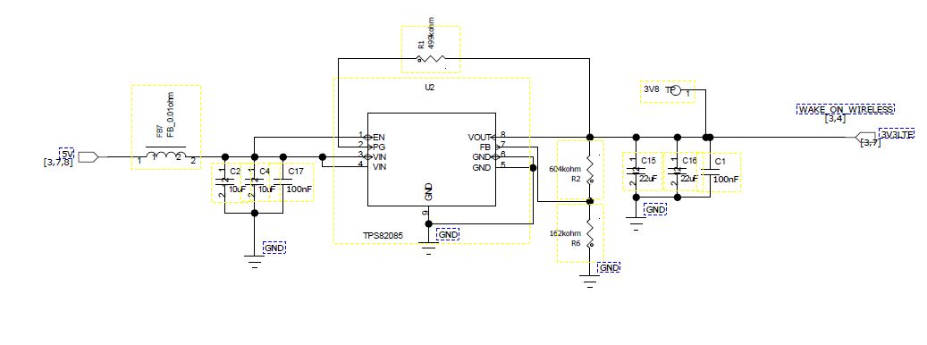
Other Parts Discussed in Thread: TPS82085, TPS63020

Hi Ti,

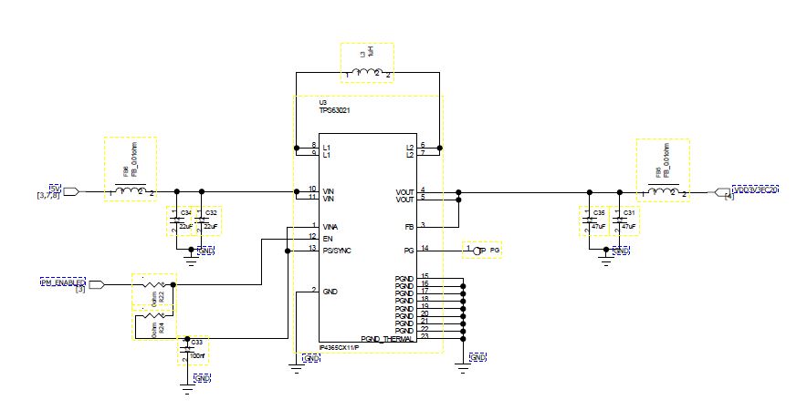
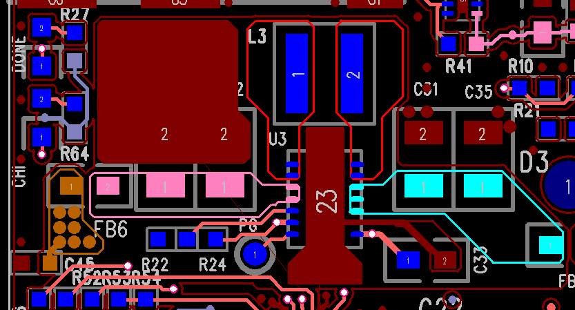
I have tested the prototype new design that uses TPS63021 power management IC and encountered some switching noise coming out from the IC and the coil inductor. Specs as below,

Vin: 5v

Vout: 3.3 (Fixed output voltage as I am using TPS63021)

Iout: design for 1A Max, max measured was able to achieve below 400mA only.

Switching Frequency: 2.4Mhz

Inductor Value: 1uH

Please help to advise further.

  • Could you share the schematic and layout ?
    Could you post a scope plot describing your problem?
  • Hi Sabrina,

    After further evaluation.

    I am using ICs using simultaneously which one is TPS63021 Output: 3.3V@1A(max) and TPS82085 Output: 3.3V@2A(max). Both take in 5V from a phone USB in OTG mode with Imax = 475mA.  The switching noise is in fact coming from both IC and not only one after I did more test, functional-wise the device is working fine if given 5V at 1A as input. 

    Please help to advise on the below.

    - Switching noise that can heard, and it gets noticeably louder when the load changes.

    - Efficiency of the two ics used.

    TPS63021 schematic & layout:-

    TPS82805 schematic & layout:-

  • The noise is most probably coming for the piezzo electric effect of the capacitors. here is a blog explaining how this could be mitigated:
    e2e.ti.com/.../how-to-reduce-acoustic-noise-of-mlccs-in-power-applications

    For the TPS63020:
    - Regarding the schematic, the input, output capacitors selection follows the datasheet recommendation. But Power save mode is disabled (PS/SYNC connected to VIN), is this intended? Is R24 populated? We need to take in account the internal connection between VIN ans VINA.
    - Regarding the layout, the component placement looks ok, but I don't see the vias around the power PAD and on the ground connection of the input capacitors, can you please confirm?
    - the efficiency curves for Vout= 3.3 V can be found in the datasheet. it gives an idea of the expected efficiency for this device.
  • Hi Electrobud,

    The TPS82085 schematic and layout look fine.

    It sounds like you only have an issue when the input current is limited to a lower value? This shows that you do not have a sufficient input power source to supply your load. A simple P=IV calculation can confirm this.
  • - Regarding the schematic, the input, output capacitors selection follows the datasheet recommendation. But Power save mode is disabled (PS/SYNC connected to VIN), is this intended? Is R24 populated? We need to take in account the internal connection between VIN ans VINA.

    Reply:

    Correct, power save mode is disabled and it is pulled high via its connection to VINA. R24 is not mounted, as EN signal is controlled by our system to enable or disable this power supply. This is to follow the power up sequence requirement of the wifi module we're using. In this case where power save mode is disabled, can it cause any issues? It is only to lower power consumption at lower loads, correct? any other issues can be caused if PS mode is disabled?

    - Regarding the layout, the component placement looks ok, but I don't see the vias around the power PAD and on the ground connection of the input capacitors, can you please confirm?

    Reply:

    There are vias at the input capacitors, they dont show because of the ground copper pour.
  • "can it cause any issues? It is only to lower power consumption at lower loads, correct? "
    -> correct when power save mode is disabled the the efficiency is worse, no issues are expected.

    There are vias at the input capacitors, they don't show because of the ground copper pour.
    -> ok if you have the necessary vias
  • I would like to highlight is I am actually using TPS63021, which has a fixed output voltage of 3.3v. Do I need to use any specific configurations other than your above recommendations?
  • no the recommendation are valid for the TPS63021 as well. both are the same device one is adjustable one fixed output voltage.

    did you try try to increase the the input power available for the devices?